Categories
Heating, Ventilation and Air Conditioning

nsxb22082a.pdf

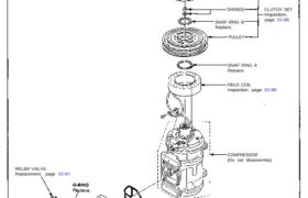
Compressor Illustrated Index RELIEF VALVE Replacement, page 22-87 O-RING Replace. SUCTION SERVICE VALVE 26 N-m (2.6 kg-m, 19 Ib-ft) CENTER BOLT PRESSURE PLATE SHIM(S) SNAP RING B Replace. PULLEY CLUTCH SET Inspection, page 22-85 SNAP RING A Replace. FIELD COIL Inspection, page 22-85 COMPRESSOR (Do not disassembly) Attachments nsxb22082a (44 kB)

Categories
Electrical

nsxb23010a.pdf

Relay and Control Unit Locations Rear Bulkhead PGM-FI MAIN RELAY THROTTLE VALVE CONTROL MOTOR RELAY Wire colors: BLK, YEL/BLK, GRN/RED, and WHT/BLU TCS CONTROL UNIT TRANSMISSION CONTROL MODULE (TCM) (A/T) PULSE UNIT (M/T) DASH LIGHTS BRIGHTNESS CONTROL UNIT FAN CONTROL UNIT ECM RETRACTABLE HEADLIGHT CONTROL UNIT INTERLOCK CONTROL UNIT (A/T) FUEL PUMP RELAY Wire colors: […]

Categories
Body

nsxb20081a.pdf

Roof Index ROOF HOOK STOP (see page 20-94) SHIM REAR RECEIVER DAMPER SHIM REAR RECEIVER SWITCH SIDE LOCK RELEASE KNOB ROOF SIDE LOCK Replacement, page 20-83 ROOF LOCK GUIDE Replacement, page 20-90 FRONT LOCK RECEIVER Replacement, page 20-92 Adjustment, page 20-92 ROOF SIDE LOCK HANDLE REAR ROOF STOP GUIDE Replacement, page 20-91 REAR LOCK RECEIVER […]

Categories
Electrical

nsxb23088a.pdf

Ignition System Component Local IGNITION TIMING CONTROL SYSTEM Description, page 23-89 Inspection, page 23-91 (’94-’96) (’91-’93). Troubleshooting, section 11 NOISE CONDENSER Test, page 23-97 SPARK PLUG (6) Inspection, page 23-96 TEST TACHOMETER CONNECTOR SERVICE CHECK CONNECTOR (2-P) (Connector color: BLU) CRANKSHAFT POSITION/CYLINDER POSITION (CKP/CYP) SENSOR Troubleshooting, section 11 Replacement, section 5IGNITION COIL (6)Removal, page 23 […]

Categories
Uncategorized

nsx15index.pdf

Differential Manual Transmission Special Tools 15−2. . . . . . . . . . . . . . . . . . . . . . . . . . . . . . . . . . . . . . . . . . . Component Location Index 15−3. . . . […]

Categories
Electrical

nsxb23238a.pdf

Stereo Sound System Unit Removal SRS components are located in this area. Review the SRS component locations, precautions, and procedures in the SRS section 24 before performing repairs or ser- vice. 1. Remove the clock (see page 23-231). 2. Remove the two screws behind the clock, then remove the center air vent (see section 20). […]

Categories
Fuel & Emissions

nsxb11150a.pdf

Intake Air System Throttle Cable Inspection/Adjustment 1. Remove the accelerator position sensor cover. 2. Check that the throttle cable operates smoothly with no binding or sticking. Repair as necessary. 3. Check cable free play at the throttle linkage. Cable deflection should be 10 – 12 mm (0.39 – 0.47 in.). ACCELERATOR POSITION SENSOR COVER DEFLECTION […]

Categories
Cooling

nsxb10002a.pdf

Cooling Illustrated Index System is under high pressure when the engine is hot. To avoid danger of releasing scalding engine coolant, remove the cap only when the engine is cool. Total Cooling System Capacity: Including expansion tank 2.1 (2.2 US qt. 1.8 Imp qt) 5 M/T: 16.0 (17.0 US qt, 14.1 Imp qt) 4 A/T: […]

Categories
Electrical

nsxb23310a.pdf

Security Alarm System Component Location Index SRS components are located in this area. Review the SRS component locations, precautions, and procedures in the SRS section (24) before performing repairs or ser- vice. RIGHT REAR SIDE MARKER LIGHT Replacement, page 23-197 PASSENGER’S DOOR KEY CYLINDER SWITCH Test, page 23-267 Replacement, section 20 STEREO RADIO/ CASSETTE PLAYER […]

Categories
Electrical

nsxb23120a.pdf

Radiator and Condenser Fan Controls Radiator Fan Control Sensor Test NOTE: Bleed air from the cooling system after install- ing the radiator fan control sensor (see section 10). 1. Remove the radiator fan control sensor from the thermostat cover. 2. Suspend the radiator fan control sensor in a con- tainer of coolant as shown. THERMOMETER […]