Intake Air System
Throttle Cable
Inspection/Adjustment
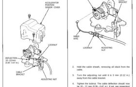
1. Remove the accelerator position sensor cover.
2. Check that the throttle cable operates smoothly with
no binding or sticking. Repair as necessary.
3. Check cable free play at the throttle linkage. Cable
deflection should be 10 – 12 mm (0.39 – 0.47 in.).
ACCELERATOR
POSITION
SENSOR COVER
DEFLECTION
10 – 12 mm
(0.39 – 0.47 in.)
LOCKNUT
CABLE
BRACKET
ADJUSTING NUT
4. If deflection is not within specs, loosen the locknut,
turn the adjusting nut until the deflection is as spec-
ified then retighten the locknut.
Installation
1. Rotate the throttle linkage counterclockwise, then
install the throttle cable in the throttle linkage and
install the cable housing in the cable bracket.
THROTTLE LINKAGE
CABLE
BRACKET
INNER
WIRE
LOCKNUT ADJUSTING
NUT
2. Hold the cable sheath, removing all slack from the
cable.
3. Turn the adjusting nut until it is 3 mm (0.12 in.)
away from the cable bracket.
4. Tighten the locknut. The cable deflection should now
be 10 – 12 mm (0.39 – 0.47 in.). If not, see inspection/
adjustment.
LOCKNUT
9.8 N-m
(1.0 kgf-m,
7.2 Ibf-ft)
ADJUSTING
NUT
CABLE
BRACKET
3 mm
(0.12 in.)
Throttle Cable
Inspection/Adjustment
1. Remove the accelerator position sensor cover.
2. Check that the throttle cable operates smoothly with
no binding or sticking. Repair as necessary.
3. Check cable free play at the throttle linkage. Cable
deflection should be 10 – 12 mm (0.39 – 0.47 in.).
ACCELERATOR
POSITION
SENSOR COVER
DEFLECTION
10 – 12 mm
(0.39 – 0.47 in.)
LOCKNUT
CABLE
BRACKET
ADJUSTING NUT
4. If deflection is not within specs, loosen the locknut,
turn the adjusting nut until the deflection is as spec-
ified then retighten the locknut.
Installation
1. Rotate the throttle linkage counterclockwise, then
install the throttle cable in the throttle linkage and
install the cable housing in the cable bracket.
THROTTLE LINKAGE
CABLE
BRACKET
INNER
WIRE
LOCKNUT ADJUSTING
NUT
2. Hold the cable sheath, removing all slack from the
cable.
3. Turn the adjusting nut until it is 3 mm (0.12 in.)
away from the cable bracket.
4. Tighten the locknut. The cable deflection should now
be 10 – 12 mm (0.39 – 0.47 in.). If not, see inspection/
adjustment.
LOCKNUT
9.8 N-m
(1.0 kgf-m,
7.2 Ibf-ft)
ADJUSTING
NUT
CABLE
BRACKET
3 mm
(0.12 in.)