Category: Fuel & Emissions
nsxd11141a.pdf
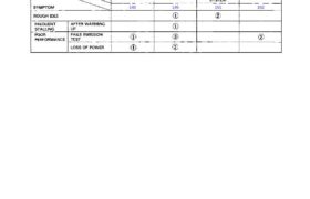
Emission Control System System Troubleshooting Guide NOTE: Across each row in the chart, the sub-systems that could be sources of a symptom are ranked in the order they should be inspected starting with . Find the symptom in the left column, read across to the most likely source, then refer to the page listed at […]
nsxd11096a.pdf
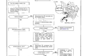
Idle Control System Troubleshooting Flowchart Neutral Switch Signal (M/T) This signals the ECM when the transmission is in neutral. Inspection of neutral switch signal. Connect the test harness be- tween the ECM and connectors (see page 11-37). Turn the ignition switch ON. Measure voltage between B7 (+) terminal and A26 (-) terminal in neutral position. […]
nsxe11103a.pdf
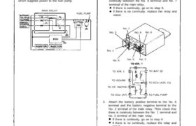
Main Relay Description The main relay actually contains two individual relays. This relay is installed behind the passengers seat back panel. One relay is energized whenever the ignition is on which supplies the battery voltage to the ECU, power to the injectors, and power for the second relay. The second relay is energized for 2 […]
nsxe11134a.pdf
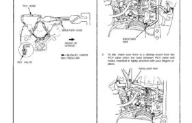
Emission Control System Positive Crankcase Ventilation System Description The Positive Crankcase Ventilation (PCV) system is designed to prevent blow-by gas from escaping to the atmosphere. The PCV valve contains a spring-loaded plunger. When the engine starts, the plunger in the PCV valve is lifted in proportion to intake manifold vacuum and the blow-by gas is […]
nsxb11143a.pdf
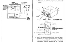
PGM-FI Main Relay Description The PGM-FI main relay actually contains two individual relays. The relay is located behind the passenger’s seat back panel. One relay is energized whenever the ignition is on which supplies the battery voltage to the ECM, power to the fuel injectors, and power for the second relay. The second relay is […]
nsxb11124a.pdf
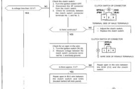
Idle Control System Clutch Switch Signal (M/T) This signals the ECM when the clutch is engaged. Inspection of clutch switch signal. Check for an open in the circuit: 1. Turn the ignition switch ON (II). 2. Measure voltage between ECM connector terminals C4 and A26. Is voltage less than 1.0 V? Check for short in […]
nsxb11119a.pdf
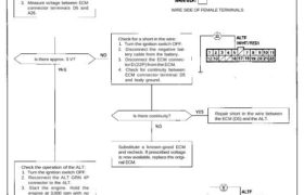
Alternator (ALT) FR Signal This signals the ECM when the Alternator (ALT) is charging. Inspection of ALT FR Signal. ECM CONNECTORS WIRE SIDE OF FEMALE TERMINALS Check for a short in the wire: 1. Turn the ignition switch OFF. 2. Disconnect the negative bat- tery cable from the battery. 3. Disconnect the ECM connec- tor […]
nsxe11066a.pdf
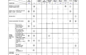
Idle Control System NOTE: Across each row in the chart, the sub systems that could be sources of a symptom are ranked in the order they should be inspected, starting with . Find the symptom in the left column, read across to the most likely source, then refer to the page listed at the top […]
nsxd11115a.pdf
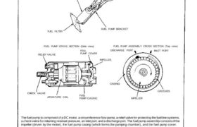
Fuel Pump Description Because of its compact impeller design, the fuel pump is installed inside the fuel tank, thereby saving space and simplify- ing the fuel line system. FUEL PUMP FUEL PUMP BRACKET FUEL FILTER FUEL PUMP CROSS SECTION (Side view) RELIEF VALVE FEUL PUMP COVER FUEL PUMP ASSEMBLY CROSS SECTION (Top view) DISCHARGE PORT […]
nsxe11078a.pdf
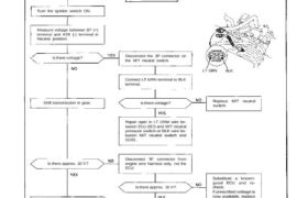
Idle Control System Troubleshooting Flowchart M/T Neutral Switch Signal This signals the PGM-FI ECU when the transmission is in Neutral. Inspection of M/T neutral Switch Signal Connect the ECU test harness between the ECU and connector (page 11-21). 0V 10V B7 A26 Turn the ignition switch ON. Measure voltage between B7 (+) terminal and A26 […]