Idle Control System
Troubleshooting Flowchart Neutral Switch Signal (M/T)
This signals the ECM when the transmission is in neutral.
Inspection of neutral switch
signal.
Connect the test harness be-
tween the ECM and connectors
(see page 11-37).
Turn the ignition switch ON.
Measure voltage between B7 (+)
terminal and A26 (-) terminal in
neutral position.
Is there voltage?
Shift transmission in gear.
Is there approx. 10 V?
Neutral switch signal is OK.
Replace neutral switch (see sec-
tion 13).
Is there approx. 10 V?
Reconnect “B” connector to
engine wire harness and discon-
nect 3P connector on the neutral
switch.
Is there approx. 10 V?
Disconnect “B” connector from
engine wire harness only, not the
ECM.
Repair open in LT GRN wire be-
tween ECM (B7) and neutral
switch or BLK wire between
neutral switch and G101
(located at right middle of
engine).
Is there voltage?
Connect LT GRN terminal to BLK
terminal.
Disconnect the 3P connector on
the neutral switch.
Replace neutral switch
(see section 13).
NEUTRAL SWITCH
LT GRN BLK
Substitute a known-
good ECM and re-
check.
If prescribed voltage is
now available, replace
the original ECM.
Repair short in LT GRN
wire between ECM
(B7) and the neutral
switch.
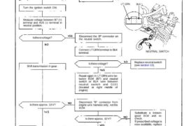