Alternator (ALT) FR Signal
This signals the ECM when the Alternator (ALT) is charging.
Inspection of ALT FR Signal.
ECM CONNECTORS
WIRE SIDE OF FEMALE TERMINALS
Check for a short in the wire:
1. Turn the ignition switch OFF.
2. Disconnect the negative bat-
tery cable from the battery.
3. Disconnect the ECM connec-
tor D (22P) from the ECM.
4. Check for continuity between
ECM connector terminal D5
and body ground.
Is there approx. 5 V?
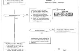
Check for a short in the circuit:
1. Disconnect the GRN 4P con-
nector from the ALT.
2. Turn the ignition switch ON (II).
3. Measure voltage between ECM
connector terminals D5 and
A26.
Is there continuity? Repair short in the wire betweenthe ECM (D5) and the ALT.
Substitute a known-good ECM
and recheck. If prescribed voltage
is now available, replace the origi-
nal ECM.
Check the operation of the ALT:
1. Turn the ignition switch OFF.
2. Reconnect the ALT GRN 4P
connector to the ALT.
3. Start the engine. Hold the
engine at 3,000 rpm with no
load (A/T in position,
M/T in neutral) until the radiator
fan comes on, then let it idle.
4. Measure voltage between ECM
connector terminals D5 and
A26.
Does the voltage decrease when
head lights and rear defogger are
turned on?
ALT FR signal is OK.
(To page 11-120)
This signals the ECM when the Alternator (ALT) is charging.
Inspection of ALT FR Signal.
ECM CONNECTORS
WIRE SIDE OF FEMALE TERMINALS
Check for a short in the wire:
1. Turn the ignition switch OFF.
2. Disconnect the negative bat-
tery cable from the battery.
3. Disconnect the ECM connec-
tor D (22P) from the ECM.
4. Check for continuity between
ECM connector terminal D5
and body ground.
Is there approx. 5 V?
Check for a short in the circuit:
1. Disconnect the GRN 4P con-
nector from the ALT.
2. Turn the ignition switch ON (II).
3. Measure voltage between ECM
connector terminals D5 and
A26.
Is there continuity? Repair short in the wire betweenthe ECM (D5) and the ALT.
Substitute a known-good ECM
and recheck. If prescribed voltage
is now available, replace the origi-
nal ECM.
Check the operation of the ALT:
1. Turn the ignition switch OFF.
2. Reconnect the ALT GRN 4P
connector to the ALT.
3. Start the engine. Hold the
engine at 3,000 rpm with no
load (A/T in position,
M/T in neutral) until the radiator
fan comes on, then let it idle.
4. Measure voltage between ECM
connector terminals D5 and
A26.
Does the voltage decrease when
head lights and rear defogger are
turned on?
ALT FR signal is OK.
(To page 11-120)
Idle Control System
Alternator (ALT) FR Signal
(From page 11-119)
ALT GRN 4P CONNECTOR
Check for an open in the wire:
1. Turn the ignition switch OFF.
2. Disconnect the negative battery
cable from the battery.
3. Disconnect the ECM connec-
tor D (22P) from the ECM.
4. Disconnect the GRN 4P con-
nector from the ALT.
5. Connect No. 2 terminal to body
ground with a jumper wire.
6. Check for continuity between
ECM connector terminal D5
and body ground.
WIRE SIDE OF FEMALE TERMINALS
ECM CONNECTOR D (22P)
Is there continuity? Repair open in the wire betweenthe ECM (D5) and the ALT.
WIRE SIDE OF FEMALE TERMINALS
See the ALT inspection (see
section 23).