Category: Cylinder Head & Valve Train
nsxd06020a.pdf
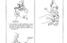
1. Disconnect the 2P connector from the VTEC solenoid valve. 2. Measure resistance between the YEL (front) or BLU/YEL (rear) terminal and body ground. Resistance: approx 14—30 ohms 4. If filters are normal, push the VTEC solenoid valve with your finger and check its movement. FILTER Replace. YEL (front) or BLU/YEL (rear) 3. If the […]
nsxb06009a.pdf
Valve Clearance Adjustment NOTE: Valves should be adjusted cold, when the cylinder head temperature is less than 100°F (38°C). Adjustment is the same for both intake and exhaust valves. Adjust valve clearance at TDC of each cylinder. Do not rotate the engine counterclockwise. The tim- ing belt could jump a tooth on the camshaft pulleys. […]
nsxb06038a.pdf
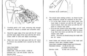
Valve Seats Reconditioning 1. Renew the valve seats in the cylinder head using a valve seat grinder. NOTE: If guides are worn (see page 6-39), replace them (see page 6-40) before grinding the valve seats. 2. Carefully grind a 45° seat, removing only enough material to ensure a smooth and concentric seat. 3. Bevel the […]
nsxd06040a.pdf
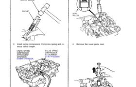
VALVE SPRING COMPRESSOR Snap-on CF711 Valves, Valve Springs and Valve Seals Replacement NOTE: Identify valves and valve springs as they are re- moved so that each item can be reinstalled in its original position. 1. Using an appropriate-sized socket and plastic mallet, lightly tap the valve retainer to loosen the valve keep- ers before installing […]
nsxb06039a.pdf
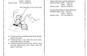
Valve Guides Valve Movement Measure the guide-to-stem clearance with a dial indicator while rocking the stem in the direction of normal thrust (wobble method). Intake Valve Stem-to-Guide Clearance: Standard (New): 0.05 — 0.11 mm (0.002 — 0.004 in) Service Limit: 0.16 mm (0.006 in) Exhaust Valve Stem-to-Guide Clearance: Standard (New): 0.10 — 0.16 mm (0.004 […]
nsxd06049a.pdf
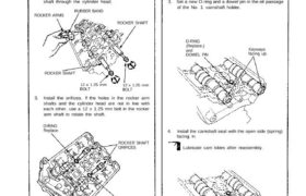
Camshafts Installation CAUTION: Valve locknuts should be loosened and ad- justing screws backed off before installation. 1. After wiping down the cam and journals in cylinder head, lubricate both surfaces and install camshaft. 2. Turn the camshaft until its keyway is facing up. (No. 1 cylinder TDC). 3. Set a new O-ring and a dowel […]
nsxb06007a.pdf
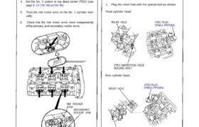
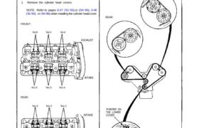
Rocker Arms Manual Inspection 1. Remove the ignition coil covers (see page 6-15 (’91-’93) or (’94-’96) 2. Remove the ignition coils (see page 6-15 (’91-’93)or (’94-’96). 3. Remove the cylinder head covers. NOTE: Refer to pages 6-47 (’91-’93) or (’94-’96) ,48 (’91-’93) or (’94-’96) when installing the cylinder head cover. 4. Set the No. 1 […]
nsxb06043b.pdf
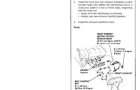
Cylinder Heads Installation Install the cylinder heads in the reverse order of removal: • Always use new head gaskets. • Cylinder heads and engine block surface must be clean. • Turn the crankshaft so that No. 1 piston is at TDC (see page 6-19). • Do not use the middle cover and lower cover for […]
nsxb06024a.pdf
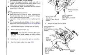
Cylinder Heads Removal Engine removal is not required for this procedure. Make sure jacks and safety stands are placed properly and hoist brackets ere attached to cor- rect positions on the engine. CAUTION: Use a fender cover (special tool) to avoid damaging painted surfaces. Unplug the wiring connectors carefully while holding the connector portion to […]
nsxb06015a.pdf
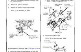
Removal NOTE: Before removing the belt, turn the crankshaft pulley so the No. 8 piston is at top dead center (TDC) (see page 6-19 (’91-’93) or (’94-’96) Inspect the water pump after removing the timing belt (see page 10-11). If it is to be reused, mark the direction of rotation on the belt. 1. Disconnect […]