Removal
Engine removal is not required for this procedure.
Make sure jacks and safety stands are
placed properly and hoist brackets ere attached to cor-
rect positions on the engine.
CAUTION:
Use a fender cover (special tool) to avoid damaging
painted surfaces.
Unplug the wiring connectors carefully while holding
the connector portion to avoid damage.
To avoid damaging the cylinder heads, wait until the
engine coolant temperature drops below 100°F
(38°C) before loosening the retaining bolts.
Do not open the engine cover when the roof panel is
stored (NSX-T open top).
NOTE:
Unspecified items are common.
Mark all wiring and hoses to avoid misconnection.
Also, be sure that they do not contact other wiring or
hoses or interfere with other parts.
Inspect the timing belt before removing the cylinder
head.
Turn the crankshaft pulley SO that the No. 1 piston is
at top dead center (see page 6-19 (’91-’93) or (’94-’96)).
1. Disconnect the negative terminal from the battery.
2. Remove the expansion tank cap.
Use care when removing the expan-
sion tank cap to avoid scalding by engine coolant
or steam.
3. Raise the car, then remove the right rear wheel/tire.
4. Drain the engine coolant (see page 10-5 ).
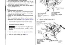
5. Remove the engine under guard, then remove the
front exhaust pipe A.
GASKETS
Replace.
FRONT EXHAUST
PIPE A
SELF-LOCKING NUT
10 x 1.25 mm
55 N·m (5.5 kg-m, 40 Ib-ft)
Replace.
SELF- LOCKING NUT
8 x 1.25 mm
22 N·m (2.2 kg-m. 16 Ib-ft)
Replace.
6. Remove the rear exhaust pipe A.
SELF- LOCKING NUT
8 x 1.25 mm
22 N·m (2.2 kg-m, 16 Ib-ft)
Replace.
REAR
EXHAUST
PIPE A
SELF-LOCKING NUT
10 x 1.25 mm
55 N·m (5.5 kg-m.
40 Ib-ft)
Replace.
GASKETS
Replace.
7. Remove the engine oil cooler base assembly (see
page 6-15 (’91-’93) or (’94-’96).
8. Lower the car.
9. Remove the strut brace (see page 5-3 ).
10. Remove the engine cover stay from the strut brace,
then set the engine cover stay between the engine
cover and rear hatch latch (NSX-T open top),
CAUTION: Use a shop tower to avoid damaging
painted surfaces.
SHOP
TOWEL
11. Relieve fuel pressure by loosening the service bolt
on the fuel filter about one turn (see section 11).
Do not smok* while working on fuel
system; Keep open flame or spark away from work
area. Drain fue1 only into an approved container.
12. Remove the fuel feed pipe and fuel return hose (see
page 5-5 (’91-’93) or (’94-’96).
13. Remove the evaporative emission (EVAP) control
canister hose and brake booster vacuum hose (see
page 5-5 (’91-’93) or (’94-’96).
14. Disconnect the breather pipe and vacuum hose, then
remove the air cleaner housing.
6 x 1.0 mm
10 N·m (1.0 kg-m, 7 lb-ftl
AIR CLEANER
HOUSING
BREATHER
PIPE
: CORROSION RESISTANT BOLT
15. Remove the Hoses, then remove the expansion tank
(see page 5-5 (’91-’93) or (’94-’96).
16. Removel the radiator hoses and heater hose (see
page 5-6 (’91-’93) or (’94-’96).
17. Disconnect the two connectors, then remove the
control box (see page 5-6 (’91-’93) or (’94-’96).
18. Remove the intake manifold plate and top cover.
INTAKE MANIFOLD
PLATE
6 x 1.0mm
12 N·m (12kg-m,
9 lb-ft)
TOP COVER
19. Remove the fuel injector covers.
6 x 1.0 mm
12 N·m (1-2 kg-m, 9 lb-ft)
FUEL INJECTOR
COVER
(cont’d)
ENGINE
COVER
STAY
Cylinder Heads
Removal
20. Remove the breather hose and water bypass hoses.
BREATHER
HOSE
WATER BYPASS
HOSES
21. Remove the ignition coil cover and harness cover.
6 x 1.0 mm
10 N-m (1.0 kg-m,
7 Ib-ft)
IGNITION COIL
COVER.
HARNESS COVER
22. Remove the positive Crankcase ventilation (PCV)
hose, vacuum hose and harness clamp.
6 x 1.0 mm
10 N-m (1.0 kg-m, 7 Ib-ft)
PCV HOSE
VACUUM HOSE
23. Remove the harness covers and ground cables from
the intake manifold.
GROUND CABLE
6 x 1.0 mm
12 N-m (1.2 kg-m, 9 Ib-ft)
GROUND CABLE
24. Remove the engine wire harness connectors and
wire harness clamps from the cylinder head and
intake manifold,
Six injector connectors
Intake air temperature (IAT) sensor connector
CKP/CYP sensor connector
Heated oxygen sensor (HO2S) connectors
Ignition control module (ICM) connectors
Engine coolant temperature (ECT) sensor connec-
tor
ECT gauge sending unit connector
ECT switch connector
Exhaust gas recirculation (EGR) valve lift sensor
connector
Throttle position sensor connector
Engine oil pressure gauge sending unit connector
Knock sensor connector
VTEC solenoid valve connectors
VTEC pressure switch connectors
Engine oil pressure switch connector
Alternator connector
Alternator terminal
Throttle body 6P connector
25. Remove the ignition coils and connector.
26. Remove the EGR pipe and intake manifold assem-
bly.
8 x 1.25mm
22 N·m (2.2 kg-m, 16 Ib-ft)
6 x 1.0 mm
12 N·m (1.2 kg-m,
9 lb-ft)
GASKETS
Replace.
INTAKE
MANIFOLD
ASSEMBLY
GASKET
Replace.
27. Loosen the adjusting nut and idler pulley center nut,
then remove the air conditioning compressor belt
(see page 6-17(’91-’93) or (’94-’96)).
28. Remove the cover, adjusting bolt, mounting bolt
and mounting nut, then remove the alternator belt
and alternator.
COVER
MOUNTING BOLT
10 x 1.25 mm
45 N·m (4.5 kg·m,
33 Ib-ft)
MOUNTING NUT
10 x 1.25 mm
45 N·m (4.5 kg·m.
33 Ib·ft)
ALTERNATOR
BELT
29. Disconnect the knock sensor connector, then remove
the wire holder.
6 x 1.0 mm
12N·m (1.2 kg-m, 9 Ib-ft)
KNOCK SENSOR
WIRE HOLDER
(cont’d)
6 x 1.0 mm
12 N·m (1.2 kg-m, 9 Ib-ft)
ADJUSTING
BOLT
Cylinder Heads
Removal (cont’d)
30. Remove the water passage. 32. Remove the alternator bracket stiffener (see page 6-16
(’91-’93) or (’94-’96).
33. Remove the alternator bracket.
8 x 1.25 mm
22 N·m (2.2 kg-m, 16 Ib-ft)
ALTERNATOR
BRACKET
10 x 1,25 mm
45N·m (4.5 kg-m,
33 Ib-ft)
34. Remove the timing belt (see page 6-15 (’91-’93) or (’94-’96)).
the timing belt
35. Remove the camshaft pulleys.
RETAINING
BOLTS CAMSHAFT PULLEYS
GROUND
CABLE
WASHER
CYLINDER HEAD
COVER
31. Remove the cylinder head covers.
0-RINGS
Replace.
CONNECTING PIPE
WATER PASSAGE
8 x 1.25 mm
22 N·m (2.2 kg-m, 16 Ib-ft)
36. Remove the front and rear back covers.
REAR BACK
COVER
RUBBER SEALS
FRONT BACK
COVER
37. Loosen the rocker arm locknuts and the adjusting
screws.
38. Remove the camshaft holder plates, camshaft holders
and camshafts.
FRONT INTAKE
CAMSHAFT
CAMSHAFT HOLDER
PLATES
RUBBER SEAL
FRONT EXHAUST
CAMSHAFT
OIL SEALS
Replace.
39. Remove the cylinder head bolts, then remove the
cylinder head.
CAUTION: To prevent warpage, unscrew the bolts
in sequence 1/3 turn at a time; repeat the sequence
until all bolts are loosened.
CYLINDER HEAD BOLTS LOOSENING SEQUENCE
NOTE: Separate the cylinder head from the block
with a flat blade screwdriver as shown.
40. Remove the front and rear exhaust manifolds (see
page 9-4).