Installation
CAUTION: Valve locknuts should be loosened and ad-
justing screws backed off before installation.
1. After wiping down the cam and journals in cylinder
head, lubricate both surfaces and install camshaft.
2. Turn the camshaft until its keyway is facing up. (No.
1 cylinder TDC).
3. Set a new O-ring and a dowel pin in the oil passage
of the No. 1 camshaft holder.
O-RING
(Replace.)
and
DOWEL PIN
Keyways
facing up.
4. Install the camshaft seal with the open side (spring)
facing in.
Lubricate cam lobes after reassembly.
CAMSHAFT SEAL
Seal housing surface should be dry.
Apply a light coat of oil to camshaft
and inner lip of seal. (cont’d)
After installing the rocker shaft orifice, try to
turn the rocker shaft to make sure that the
orifice has been inserted in the hole of rocker
shaft correctly. If the orifice is in place, it should
not turn.
Remove the rubber bands after installing the
rocker arms.
O-RING
Replace.
ROCKER SHAFT
ORIFICES
O-RING
Replace.
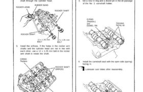
3. Install the orifices. If the holes in the rocker arm
shafts and the cylinder head are not in line with
each other, use a 12 x 1.25 mm bolt in the rocker
arm shaft to rotate the shaft.
ROCKER SHAFT
12 x 1.25 mm
BOLT
12 x 1.25 mm
BOLT
ROCKER SHAFT
ROCKER ARMS
RUBBER BAND
1. Install the lost motion assemblies.
2. Install the rocker arms while passing the rocker arm
shaft through the cylinder head.
Rocker Arms
Installation
Valve adjusting lockouts should be loosened and
adjusting screws backed off before installation.
The component parts must be installed in the
original locations.
Install the rocker arms in the reverse order of removal:
CAUTION:
Camshafts
Installation (cont’d)
5. Apply liquid gasket to the head mating surfaces of
the No. 1 and the No. 4 camshaft holders.
Apply liquid gasket to the shaded areas.
6. Place the camshaft holders.
REAR:
No. 4 No. 3 No. 2 No. 1
CAMSHAFT CAMSHAFT CAMSHAFT CAMSHAFT
HOLDER HOLDER HOLDER HOLDER
REAR:
7. Place the cam holder pipes.
8. Tighten each bolt two turns at a time in the sequence
shown below to insure that the rockers do not bind
on the valves.
NOTE: Apply clean engine oil to 8 mm bolt threads.
Specified torque:
8 mm x 1.25 mm bolts:
22 N.m (2.2 kg-m, 16 Ib-ft)
6 mm x 1.0 mm bolts:
10 N.m (1.0 kg-m, 7 Ib-ft)
CAMSHAFT HOLDER BOLT TORQUE SEQUENCE
FRONT:
NOTE:
“F” or “R” marks are stamped on the camshaft
holders.
The arrows must be pointing to the timing belt
side.
Set two dowel pins in each camshaft holder.
FRONT:
No. 4 No. 3 No. 2 No. 1
CAMSHAFT CAMSHAFT CAMSHAFT CAMSHAFT
HOLDER HOLDER HOLDER HOLDER
9. Install the CKP/CYP sensor on the front cylinder
head.
CKP/CYP SENSOR
6 x 1.0 mm
12 N.m (1.2 kg-m, 9 Ib-ft)
10. Install the front and rear timing cover plates.
RUBBER SEALS
REAR COVER
PLATE
6x 1.0 mm
12 N.m (1.2 kg-m.
9 Ib-ft) RUBBER SEAL
FRONT COVER
PLATE
RUBBER SEALS
11. Insert the dowel pins in the camshaft pulley.
12. Install the camshaft pulleys then tighten the retain-
ing bolts to the torque specified.
NOTE: To set the camshafts at TDC, align the
camshaft holes with the camshaft holder pipe holes
and insert 5.0 mm pin punches as shown.
CAMSHAFT PULLEYS
5.0 mm
PIN PUNCHES
RETAINING BOLTS
10 x 1.25 mm
70 N.m (7.0 kg-m, 51 Ib-ft)
13. Install the timing belt (page 6-25, 26).
14. Adjust the valve clearance (page 6-54).
15. Inspect the rocker arms (pages 6-52, 53).
16. After installation, check that hoses and connectors
are installed correctly.
Prior to installing the cylinder head cover, apply
a thin layer of liquid gasket to the mating surface
of the cylinder head cover and rubber seals to
prevent the rubber seal from falling off.
After installation, fill the engine with oil up to the
specified level, run the engine for more than 3
minutes, then check for oil leakage.
NOTE: