Rocker Arms Manual Inspection
1. Remove the ignition coil covers (see page 6-15 (’91-’93)
or (’94-’96)
2. Remove the ignition coils (see page 6-15 (’91-’93)or (’94-’96).
3. Remove the cylinder head covers.
NOTE: Refer to pages 6-47 (’91-’93) or (’94-’96) ,48 (’91-’93)
or (’94-’96) when installing the cylinder head cover.
4. Set the No. 1 piston at top dead center (TDC) (see
page 6-19 (’91-’93) or (’94-’96).
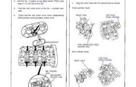
5. Push the mid rocker arms on the No. 1 cylinder man-
ually.
6. Check that the mid rocker arms move independently
of the primary and secondary rocker arms.
MID ROCKER
ARM
SECONDARY
ROCKER ARM
PRIMARY
ROCKER ARM
7. Check the mid rocker arms of each cylinder at TDC.
If a mid rocker arm does not move, remove the
mid, primary and secondary rocker arms as an
assembly and check that the pistons in the mid
and primary rocker arms move smoothly.
Replace the rocker arms as an assembly if there
is any abnormality.
Rocker Arms Inspection Using
Special Tools
CAUTION:
Before using the special tool, make sure that the air
pressure gauge on the air compressor indicates over
250 kPa (2.5 kg/cm2. 36 psi).
Inspect the valve clearance before rocker arm inspec-
tion.
Cover the timing belt with a shop towel to prevent
getting oil on the belt.
Check the mid rocker arms of each cylinder at TDC.
1. Plug the relief hole with the special tool as shown.
Front cylinder head:
RELIEF HOLE VTEC PLUG
07MAJ–PR7020A
VTEC INSPECTION HOLE
SEALING BOLT
Rear cylinder head:
RELIEF HOLE
VTEC PLUG
07MAJ–PR7020A
VTEC INSPECTION HOLE
SEALING BOLT
(cont’d)
1. Remove the ignition coil covers (see page 6-15 (’91-’93)
or (’94-’96)
2. Remove the ignition coils (see page 6-15 (’91-’93)or (’94-’96).
3. Remove the cylinder head covers.
NOTE: Refer to pages 6-47 (’91-’93) or (’94-’96) ,48 (’91-’93)
or (’94-’96) when installing the cylinder head cover.
4. Set the No. 1 piston at top dead center (TDC) (see
page 6-19 (’91-’93) or (’94-’96).
5. Push the mid rocker arms on the No. 1 cylinder man-
ually.
6. Check that the mid rocker arms move independently
of the primary and secondary rocker arms.
MID ROCKER
ARM
SECONDARY
ROCKER ARM
PRIMARY
ROCKER ARM
7. Check the mid rocker arms of each cylinder at TDC.
If a mid rocker arm does not move, remove the
mid, primary and secondary rocker arms as an
assembly and check that the pistons in the mid
and primary rocker arms move smoothly.
Replace the rocker arms as an assembly if there
is any abnormality.
Rocker Arms Inspection Using
Special Tools
CAUTION:
Before using the special tool, make sure that the air
pressure gauge on the air compressor indicates over
250 kPa (2.5 kg/cm2. 36 psi).
Inspect the valve clearance before rocker arm inspec-
tion.
Cover the timing belt with a shop towel to prevent
getting oil on the belt.
Check the mid rocker arms of each cylinder at TDC.
1. Plug the relief hole with the special tool as shown.
Front cylinder head:
RELIEF HOLE VTEC PLUG
07MAJ–PR7020A
VTEC INSPECTION HOLE
SEALING BOLT
Rear cylinder head:
RELIEF HOLE
VTEC PLUG
07MAJ–PR7020A
VTEC INSPECTION HOLE
SEALING BOLT
(cont’d)