NOTE:
Before removing the belt, turn the crankshaft pulley
so the No. 8 piston is at top dead center (TDC) (see
page 6-19 (’91-’93) or (’94-’96)
Inspect the water pump after removing the timing
belt (see page 10-11).
If it is to be reused, mark the direction of rotation on
the belt.
1. Disconnect the battery negative terminal first, then
the positive terminal,
2. Remove the right rear wheel/tire.
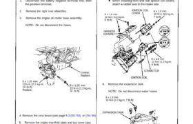
3. Remove the engine oil cooler base assembly-
NOTE: Do not disconnect the hoses.
O-RING
Replace.
8 x 1.25 mm
22 N·m (2.2 kg-m,
16 Ib-ft)
8 x 1.25 mm
22 N·m (2.2 kg-m,
16 Ib-ft)
Replace.
4. Remove the strut brace (see page 5-3 (’91-’93) or (’94-’96)
5. Remove the intake manifold plate and top cover (see
page 6-25 (’91-’93) or (’94-’96)
4. Remove the ignition coil covers, the injector cover
and the wire harness covers.
5. Remove the ignition coils and the connectors.
NOTE:
There are front and rear ignition coils and covers.
They can be identified by the mark FF (front) or
RR (rear) printed on them.
When installing front and rear ignition coil covers,
attach a rubber seal to the intake side.
6 x 1.0 mm
12 N·m (1.2 kg-m,
9 Ib-ft)
IGNITION COIL
COVER 6 x 1.0 mm10 N·m (1.0 kg-m,
7 Ib-ft)
HARNESS
COVERS
6 x 1.0 mm
12 N·m (1.2 kg-m,
9 Ib-ft)
CONNECTOR
IGNITION COIL
6. Remove the expansion tank.
NOTE: Do not disconnect water hoses.
6 x 1.0 mm
10 N·m (1.0 kg-m, 7 Ib-ft)
EXPANSION TANK
(cont’d)
Timing Belt
Removal (cont’d)
7. Remove the breather hose and the air cleaner hous-
ing (see page 6-25 (’91-’93) or (’94-’96) )
8. Disconnect the alternator connector and the termi-
nal.
9. Remove the cover, adjusting bolt, the mounting bolt
and mounting nut, then remove the alternator belt
and the alternator.
COVER6 x 1.0 mm
12 N·m (1,2 kg-m,
9 Ib-ft)
MOUNTING BOLT
10 x 1.25 mm
45 N·m (4.5 kg-m,
33 Ib-ft)ADJUSTING
BOLT
MOUNTING NUT
10 x 1.25 mm
45 N·m (4.5 kg-m,
33 Ib-ft)
ALTERNATOR
BELT
10. Remove the cylinder head covers.
Refer to page 6-47 (’91-’93) or (’94-’96) when installing.
11. Remove the two bolts from the side engine mount
near the alternator bracket. Pivot the mounting bracket
into the housing of the body.
12 x 1.25 mm
73 N·m (7.3 kg-m, 53 Ib-ft)
Replace.
12 x 1.25 mm
95 N·tn (9,5 kg-m,
69 Ib-ft)
CORROSION RESISTANT BOLT
12. Remove the transmission mount (see page 5-10 (’91-’93)
or (’94-’96) transmission mount
13. Install a brace under the engine, then tilt the engine
approximately 5 using a jack.
NOTE: Make sure to place a cushion between the
oil pan and the jack.
14. Remove the alternator bracket stiffener and dipstic
pipe.
ALTERNATOR BRACKET
STIFFENER
8 x 1.25 mm
22N·m
(2.2 kg-m,
16 lb-ft!
10 x 1.25 mm
45 N·m (4.5 kg-m,
33 Ib-ft! 6 x 1.0 mm
12N·m (1.2 kg-m, 9 Ib-ft)
DIPSTICK PIP
15. Loosen the idler pulley center nut and adjusting nut,
then remove the air conditioning (A/C) compressor
belt.
IDLER PULLEY
CENTER NUT
45 N·m (4.5 kg-m,
33 lb-ft)ADJUSTING
NUT
A/C COMPRESSOR
BELT
16. Remove the crankshaft pulley (see page 6-12 (’91-’93)
or (’94-’96)
17. Remove the rubber seal from the adjusting bolt,
then remove the middle covers and lower cover.
6 x 1.0 mm
12 N·m (1.2 kg-m.
9 Ib-ft)
LOWER COVER
RUBBER SEAL
6 x 1.0 mm
12 N·m (1.2 kg-m,
9 lb-ft) 9 x 1.25 mm
22 N·m (2.2 kg-m,
16 Ib ft)
IDLER PULLEY
ASSEMBLY
COLLAR
MIDDLE COVER
1 8 . Loosen the adjusting boll 180 0 turn. Push the ten-
sioner to remove tension from the timing belt, then
re tighten the adjusting bolt.
ADJUSTING BOLT
Do not remove. When
adjusting, loosen
it 180°.
19. Remove the timing belt from the pulleys.