Category: Electrical
Categories
nsxb23238a.pdf
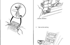
Stereo Sound System Unit Removal SRS components are located in this area. Review the SRS component locations, precautions, and procedures in the SRS section 24 before performing repairs or ser- vice. 1. Remove the clock (see page 23-231). 2. Remove the two screws behind the clock, then remove the center air vent (see section 20). […]
Categories
nsxb23310a.pdf
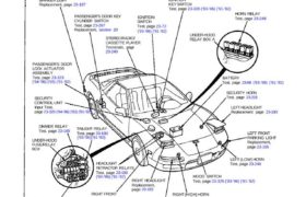
Security Alarm System Component Location Index SRS components are located in this area. Review the SRS component locations, precautions, and procedures in the SRS section (24) before performing repairs or ser- vice. RIGHT REAR SIDE MARKER LIGHT Replacement, page 23-197 PASSENGER’S DOOR KEY CYLINDER SWITCH Test, page 23-267 Replacement, section 20 STEREO RADIO/ CASSETTE PLAYER […]
Categories
nsxb23120a.pdf
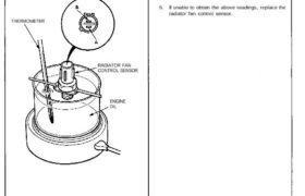
Radiator and Condenser Fan Controls Radiator Fan Control Sensor Test NOTE: Bleed air from the cooling system after install- ing the radiator fan control sensor (see section 10). 1. Remove the radiator fan control sensor from the thermostat cover. 2. Suspend the radiator fan control sensor in a con- tainer of coolant as shown. THERMOMETER […]
Categories
nsxb23093a.pdf
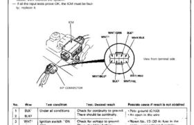
Ignition Control Module (ICM) Input Test Disconnect the 8-P connector from the ignition control module (ICM). Inspect the connector and socket terminals to be sure they are all making good contact. • If the terminals are bent, loose, or corroded, repair them as necessary, and recheck the system. • If the terminals look OK, make […]
Categories
nsxb23138a.pdf
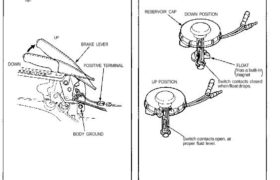
Brake Warning System Parking Brake Switch Test 1. Remove the center console, and disconnect the con- nector from the switch. 2. Check continuity between the positive terminal and body ground with the brake lever up and down. • There should be no continuity with the brake lever down. • There should be continuity with the […]
Categories
nsxe23150a.pdf
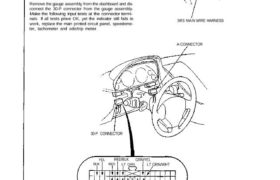
Shift Lever Position Indicator CAUTION: All SRS electrical wiring harnesses are covered with yellow outer insulation. Before disconnecting the SRS wire harness, Install the short connector on the airbus (see page 23-323). Raplace the entire affected SRS harness assembly if it has an open circuit or damaged wiring. After installation of the gauge assembly, recheck […]
Categories
nsxd23292a.pdf
Cruise Control Description The cruise control system uses mechanically and elec- trically operated devices to maintain vehicle speed at a setting selected by the driver. The cruise control unit receives command signals from the cruise control main switch and the cruise control set/resume switch. It receives information about operating conditions from the brake switch, ECM, […]
Categories
nsxb23209a.pdf
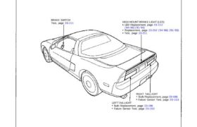
Brake Lights Component Location Index BRAKE SWITCH Test, page 23-211 HIGH MOUNT BRAKE LIGHT (LED) LED Replacement, page 23-212 (’94-’96) (’91-’93) Replacement, page 23-212 (’94-’96) (’91-’93) Test, page 23-211 RIGHT TAILLIGHT Bulb Replacement, page 23-196 Failure Sensor Test, page 23-153 LEFT TAILLIGHT Bulb Replacement, page 23-196 Failure Sensor Test, page 23-153 Attachments nsxb23209a (41 kB)
Categories
nsxe23144a.pdf
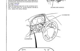
CAUTION: All SRS electrical wiring harnesses are covered with yellow outer Insulation. Before disconnecting the SRS wire harness, Install the short connector on the airbag (see page STET). Replace the entire affected SRS harness assembly if it has an open circuit or damaged wiring. After installation of the gauge assembly, recheck the operation of the […]
Categories
nsxb23091a.pdf
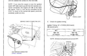
Ignition Timing Inspection SRS components are located in this area. Review the SRS component locations, precautions, and procedures in the SRS section 24 before performing repairs or service. 1. Pull out the service check connector located under the middle of the dash. Connect the BLU and BRN/ BLK terminals with the SCS service connector. 2. […]