Category: Electrical
Categories
nsxb23275a.pdf
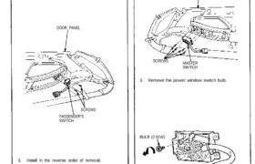
Passenger’s Switch Replacement 1. Remove the door panel (see section 20). 2. Remove the two screws, then remove the passenger’s switch from the door panel. DOOR PANEL SCREWS PASSENGER’S SWITCH 3. Install in the reverse order of removal. Switch Light Bulb Replacement 1. Remove the door panel (see section 20). 2. Remove the four screws, […]
Categories
nsxd23255a.pdf
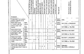
Troubleshooting NOTE: The numbers in the table show the troubleshooting sequence. Main Menu Table of Contents Troubleshooting NOTE: The numbers in the table show the troubleshooting sequence. Item to be inspected Symptom Blown No. 35 (20 А) fuse (in the under—hood fuse/relay box) Disconnected or obstructed door lock rod/linkage Driver’s door lock knob switch (In […]
Categories
nsxb23225a.pdf
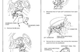
Controller Removal SRS components are located in this area. Review the SRS component locations, precautions, and procedures in the SRS section 24 before performing repairs or service. 1. Remove the dashboard lower cover, and disconnect the connectors. 2. Remove the dashboard lower pad. DASHBOARD LOWER COVER 3. Remove the tilt cover. DASHBOARD LOWER PAD TILT […]
Categories
nsxe23282b.pdf
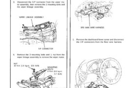
Wipers/Washers Windshield Wiper Motor Replacement 1. Open the hood and remove the cap nuts and the wiper arms. NOTE: Carefully remove the wiper arms so that they do not touch the hood. 2. Remove the windshield lower molding, hood seal and air scoop by prying off the trim clips and removing the screws (see page […]
Categories
nsxe23308a.pdf
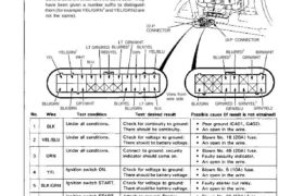
Security Alarm System Control Unit Input Test Remove the glove box to disconnect the 22-P connec- tor and 16-P connector from the control unit. Make the following input tests at the harness pins. NOTE: Recheck the connections between the 22-P con- nector and the control unit, the 16-P connector and the control unit, then replace […]
Categories
nsxb23191a.pdf
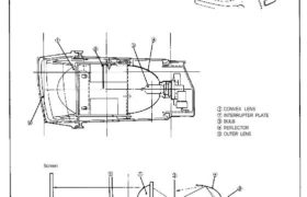
Headlights Description The light first forms basic pattern A after being interrupt- ed by the interrupter plate and passed through the con- vex lens. The interrupter plate determines the form. The outer lens distributes the light into pattern B. Screen CONVEX LENS INTERRUPTER PLATE BULB REFLECTOR OUTER LENS Attachments nsxb23191a (47 kB)
Categories
nsxb23292a.pdf
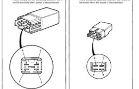
Wipers/Washers High Relay/Washer Relay Test 1. Remove the wiper high relay or the washer relay from under-hood relay box B. 2. Check continuity at the relay terminals. • There should be continuity between the C and D terminals. • There should be continuity between the A and B terminals when power and ground are connect- […]
Categories
nsxb23233a.pdf
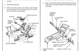
Replacement SRS components are located in this area. Review the SRS component locations, precautions, and procedures in the SRS section 24 before performing repairs or ser- vice. 1. Remove the clock (see page 23-231). 2. Remove the two screws behind the clock, then remove the center air vent (see section 20). 3. Remove the four […]
Categories
nsxb23010a.pdf
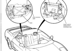
Relay and Control Unit Locations Rear Bulkhead PGM-FI MAIN RELAY THROTTLE VALVE CONTROL MOTOR RELAY Wire colors: BLK, YEL/BLK, GRN/RED, and WHT/BLU TCS CONTROL UNIT TRANSMISSION CONTROL MODULE (TCM) (A/T) PULSE UNIT (M/T) DASH LIGHTS BRIGHTNESS CONTROL UNIT FAN CONTROL UNIT ECM RETRACTABLE HEADLIGHT CONTROL UNIT INTERLOCK CONTROL UNIT (A/T) FUEL PUMP RELAY Wire colors: […]
Categories
nsxb23088a.pdf
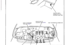
Ignition System Component Local IGNITION TIMING CONTROL SYSTEM Description, page 23-89 Inspection, page 23-91 (’94-’96) (’91-’93). Troubleshooting, section 11 NOISE CONDENSER Test, page 23-97 SPARK PLUG (6) Inspection, page 23-96 TEST TACHOMETER CONNECTOR SERVICE CHECK CONNECTOR (2-P) (Connector color: BLU) CRANKSHAFT POSITION/CYLINDER POSITION (CKP/CYP) SENSOR Troubleshooting, section 11 Replacement, section 5IGNITION COIL (6)Removal, page 23 […]