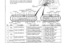
Control Unit Input Test
Remove the glove box to disconnect the 22-P connec-
tor and 16-P connector from the control unit.
Make the following input tests at the harness pins.
NOTE:
Recheck the connections between the 22-P con-
nector and the control unit, the 16-P connector
and the control unit, then replace the control unit
if all input tests prove OK.
Several different wires have the same color. They
have been given a number suffix to distinguish
them (for example YEL/GRN1 and YEL/GRN2 are
not the same).
YEL
YEL/GRN2
WHT
BLU
LT GRN/RED
RED/YEL
BLU/RED1
LT GRN/WHT
BLK/YEL
GRN YEL/BLU
BLU/GRN
BLK/BRN
GRY/WHT BLU/YEL
BLU/GRN
LT GRN
BLK
View from
wire side
22-P
CONNECTOR
SECURITY
CONTROL UNIT
16-P CONNECTOR
BLU/RED3
BLU/RED2
GRN/WHT
BRN/WHT
BLK/GRN GRN/RED
GRN/BLU
GRN/YEL1
GRN/YEL2
(cont’d)
Reconnect the 22-P and 16-P connectors to the control unit.
Main Menu Table of Contents
No. Wire Test condition Test: desired result Possible cause (¡í result is not obtained)
Under all conditions. Attach to ground: I Faulty lighting relay.
8 BLU/RED headlights should come on. ∙ Faulty lighting system.
I An open in the wire.
Under all conditions. Connect to ground: I Faulty taillight relay.
9 RED/YEL Taillights should come on. I Fautly taillight system.
I An open in the wire.
Passing switch ON. Check for voltage to ground: I Faulty passig switch.
10 LT GRN/ There should be battery voltage. I Faulty dimmer relay.
RED ∙ Faulty lighting relay.
I An open in the wire.
Reconnect the 22-P and 16-P connectors to the control unit.
No. Wire
Test condition
Test: desired result
Possible cause (if result is not obtained)
1 1 YEL/GRN2
Hood opened.
Check for voltage to ground:
There should be 1 V or less.
Hood closed.
Check for voltage to round:
There should be 5 V or more.
I Faulty hood switch. Misadjusted
hood switch.
I Poor ground (6301).
I An open in the wire.
12 BLU/GRN
Ignition key is inserted
into the ignition switch.
Check for voltage to ground:
There should be 1 V or less.
Ignition key is removed
from the ignition switch.
Check for voltage to ground:
There should be 5 V or more.
I Faulty ignition key switch.
Poor grou‘nd (G401, G402).
∙ An open in the wire.
Engine cover‘opened. Check for voltageto ground: ∙ Faulty engine cover switch.
13 BLU There should be 1 V or less. ∙ Misadjusted engine cover switch.
. I Poor ground (G401, G402).
Engine cover closed. Check for voltage to ground: ∙ An О en ¡n the wire
There should be 5 \/ or more. p ‘
BLK/BRN Under all conditions. Check for voltage to ground: I Poor ground (G404).
14 or BLK/ There should be 1 V or less. I An open in the wire,
LT GRN
Trunk key in UNLOCK. Check for voltage to ground: ∙ Faulty trunk key.
15 BRN/WHT There should be 1 V or less. I Poor ground (6501).
I An open ∣⊓ the wne.
Trunk lid opened. Check for voltage to ground: I Faulty trunk latch switch.
There should be 1 V or less. Misadjusted trunk latch switch.
16 \/\/НТ I Poor ground (6501).
Trunk lid closed.
Check for voltage to ground:
There should be 5 V or more.
I An open in the wrie.
(cont’d)
23-309
Security Alarm System
Control Unit Input Test (cont’d)
Main Menu
Table of Contents
Security Alarm System
Control Unit nput Test (cont’d)
No. Wire Test condition Test: desired result Possible cause т result is not obtained)
17 GRN/BLU Driver’s door opened. Check for voltage to ground: Faulty right door switch.
Driven: dom closed_ when the door IS oppened, An open in the Wire.
there should be 1 V or less,
Passenger’s door opened. and when the door is closed,
18 GRN/RED Passengerrs door Closed. there should be 5 V or more.
19 GRN/VEL, Driver’s door key in Check for voltage to ground: Faulty left or right door key
UNLOCK. There should be 1 V or less, swrtch.
Passenge’,s door key ¡n Poor ground (G401, G402).
2 . .
20 GFlN/YEL UNLOCK’ An open In the Wire.
21 GRN/WH`. Drive“ door key ¡n LOCK. Check for voltage to ground: Faulty left or right door key
There should be 1 V or less, switch.
22 GRYIWHT Passenger,s door key in as the door keylock Is turned Poor ground (G491, G402).
In LOCK. An open in the Wire.
LOCK.
Driver‘s door lock knob in Check for voltage to ground: Faulty left door lock knob switch.
UNLOCK. There should be 1 V or less. (built in the actuator),
2
23 BLU/RED Poor ground (G401, G402).
An open in the wire.
Passenger’s door lock knob Check for voltage to ground: Faulty right door lock knob
in UNLOCK. There should be 1 V or less. switch.
24 BLU/RED3 (built-into the actuatorl.
Poor ground (G401, G402).
An open in the wire.
23-31 0