CAUTION:
All SRS electrical wiring harnesses are covered with
yellow outer insulation.
Before disconnecting the SRS wire harness, Install
the short connector on the airbus (see page 23-323).
Raplace the entire affected SRS harness assembly
if it has an open circuit or damaged wiring.
After installation of the gauge assembly, recheck the
operation of the SRS indicator light.
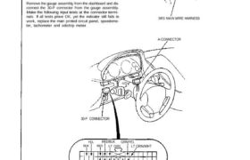
Remove the gauge assembly from the dashboard and dis-
connect the 30-P connector from the gauge assembly.
Make the following input tests at the connector termi-
nals. If all tests prove OK, yet the indicator still fails to
work, replace the main printed circuit panel, speedome-
ter, tachometer and odo/trip meter.
A-CONNECTOR (Carries the SRS indicator signal)
SRS MAIN WIRE HARNESS
A-CONNECTOR
30-P CONNECTOR
Indicator Input Test
YEL
BLK
RED/BLK
RED LT GRN
GRN/YEL
LT GRN/WHT
YEL/BLU
GRY/WHT GRN
LT BLU YEL/BLK
BRN/BLK
View from wire side
Main Menu Table of Contents
No. Wire Test condition Test: desired result Possible cause ¡if result is not obtained)
_I ELK Under all conditions. Check for continuity to ground: ∙ Poor ground (G401. G402).
There should be continuity. ∙ ∧⊓ open in the wire.
2 YEL Ignition switch ON. Check for voltage to ground: ∙ Blown No. 5 I10 A) fuse.
There should be battery voltage. ∙ An open in the wire.
FlY/WHT Shift lever in position P. Check for continuity to ground: ∙ Faulty shift position console switch.
∣∙⊺ BLU shih ‘eve’ ¡n position ∏∙ There should be contmurty. ∙ Poor ground (G491, G402).
∎ An open In the wrre.
GRN Shift lever in position N.
3 BFIN/BLK Shift lever in position 3.
GRN/VEL Shift lever in positon 2.
LT GRN/ Shift lever in position 1.
WHT
Shift lever in position D. Check for continuity to ground: ∙ Faulty shift position console
There should be continuity. switch.
4 GRN/BLU ∙ Faulty A/T control system.
∙ Poor ground (G401, G402).
∙ ∧⋂ open in the wire.
RED/ELK Lighting switch ON and Check for voltage between ∙ Faulty dashlight brightness control
5 and RED dashlight brightness con— RED/BLK and RED terminals: system.
trol dial on full bright. There should be battery voltage. ⋅ An open in the wire.
Ignition switch ON, shift Check for voltage to ground: ∙ Faulty D switch.
lever in position 2 or 3 There should be about 5 V. ∎ Faulty shift position consle
6 YEL/BLK and D switch ON. switch.
∙ Faulty A/T control system.
∙ An open in the wire.
Ignition switch ON, shift Check for voltage to ground: ∙ Faulty D switch.
lever in position 2 or 3 There should be battery voltage. ∎ Faulty shift position console
7 YEL/BLU and D switch ON. switch.
∙ Faulty A/T control system.
∙ An open in the wire.
Ignition switch ON. Check for voltage to ground: ∙ Faulty PGM-FI ECU and NT control
8 LT GRN There should be about 5 V. unit,
∙ An open in the wire.
23-151