Category: Electrical
Categories
nsxb23007a.pdf
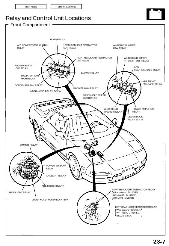
Relay and Control Unit Locations Front Compartment HORN RELAY A/C COMPRESSOR CLUTCH RELAY RADIATOR FAN LOW RELAY RADIATOR FAN HIGH RELAY CONDENSER FAN RELAY UNDER-HOOD RELAY BOX A LEFT HEADLIGHT RETRACTOR CUT RELAY WINDSHIELD WIPER LOW RELAY WINDSHIELD WIPER INTERMITTENT RELAY POWER AMPLIFIER RELAY ABS REAR FAIL-SAFE RELAY ABS FRONT FAIL-SAFE RELAY HEADLIGHT RELAY RIGHT […]
Categories
nsxb23089a.pdf
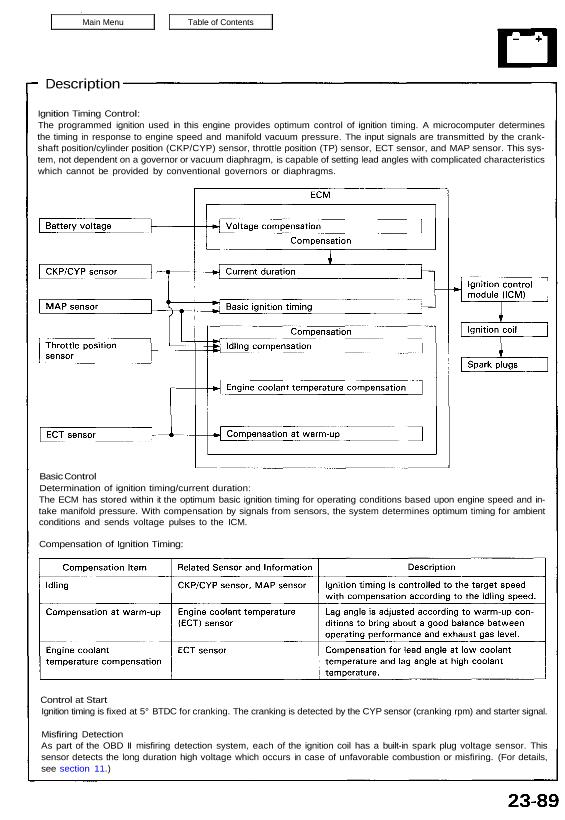
Control at Start Ignition timing is fixed at 5° BTDC for cranking. The cranking is detected by the CYP sensor (cranking rpm) and starter signal. Misfiring Detection As part of the OBD II misfiring detection system, each of the ignition coil has a built-in spark plug voltage sensor. This sensor detects the long duration high […]
Categories
nsxb23305a.pdf
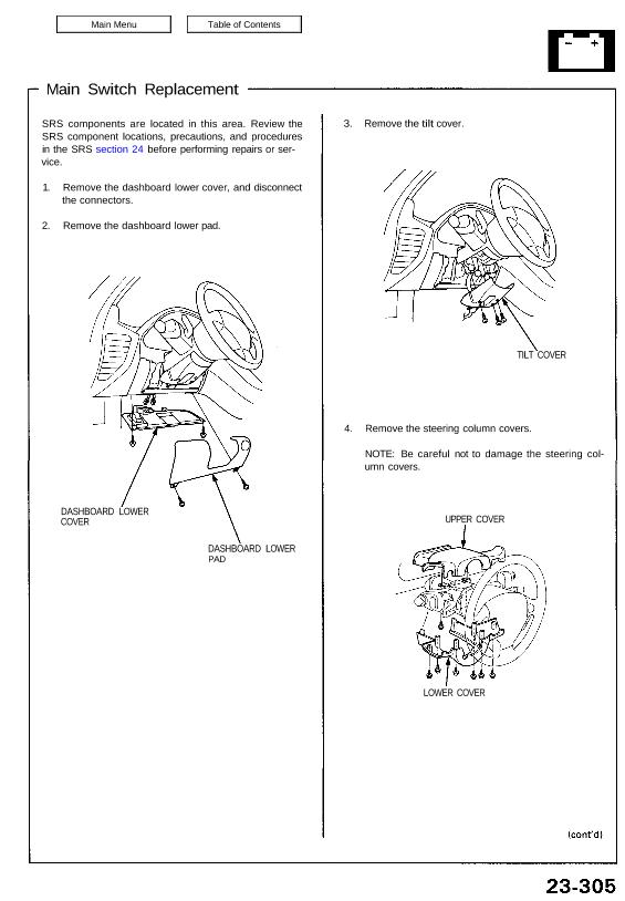
Main Switch Replacement SRS components are located in this area. Review the SRS component locations, precautions, and procedures in the SRS section 24 before performing repairs or ser- vice. 1. Remove the dashboard lower cover, and disconnect the connectors. 2. Remove the dashboard lower pad. DASHBOARD LOWER COVER DASHBOARD LOWER PAD 3. Remove the tilt […]
Categories
nsxb23186a.pdf
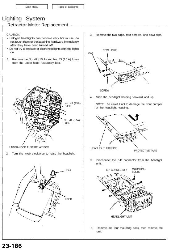
Lighting System Retractor Motor Replacement CAUTION: • Halogen headlights can become very hot in use; do not touch them or the attaching hardware immediately after they have been turned off. • Do not try to replace or clean headlights with the lights on. 1. Remove the No. 42 (15 A) and No. 43 (15 A) […]
Categories
nsxd23253a.pdf
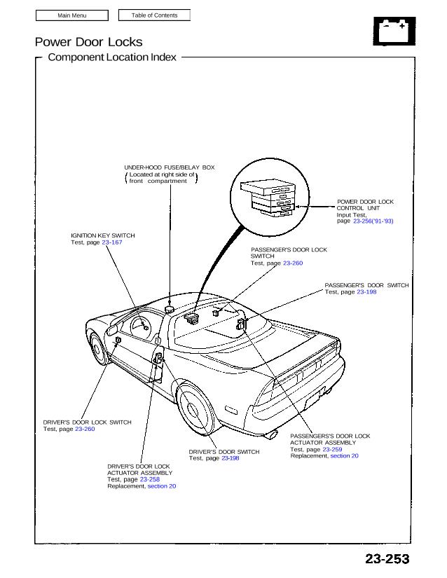
Power Door Locks Component Location Index UNDER-HOOD FUSE/BELAY BOX Located at right side of front compartment IGNITION KEY SWITCH Test, page 23-167 DRIVER’S DOOR LOCK SWITCH Test, page 23-260 DRIVER’S DOOR LOCK ACTUATOR ASSEMBLY Test, page 23-258 Replacement, section 20 DRIVER’S DOOR SWITCH Test, page 23-198 PASSENGERS’S DOOR LOCK ACTUATOR ASSEMBLY Test, page 23-259 Replacement, […]
Categories
nsxe23292a.pdf
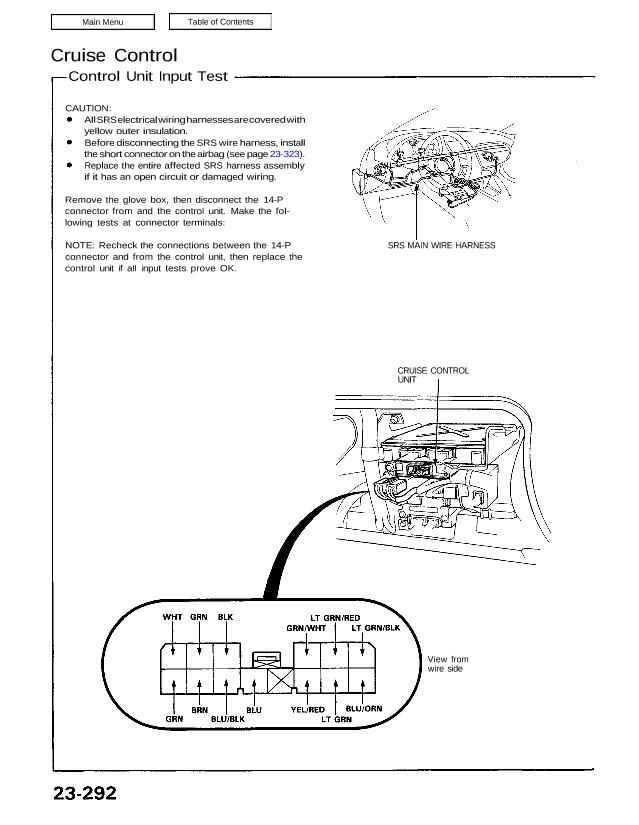
Cruise Control Control Unit Input Test CAUTION: All SRS electrical wiring harnesses are covered with yellow outer insulation. Before disconnecting the SRS wire harness, install the short connector on the airbag (see page 23-323). Replace the entire affected SRS harness assembly if it has an open circuit or damaged wiring. Remove the glove box, then […]
Categories
nsxb23221a.pdf
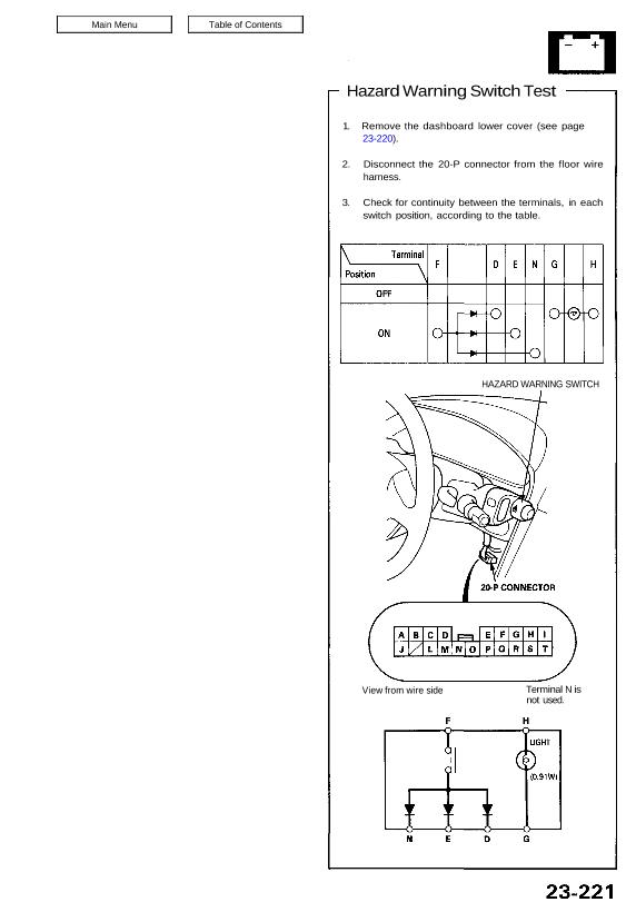
Hazard Warning Switch Test 1. Remove the dashboard lower cover (see page 23-220). 2. Disconnect the 20-P connector from the floor wire harness. 3. Check for continuity between the terminals, in each switch position, according to the table. HAZARD WARNING SWITCH View from wire side Terminal N is not used. Attachments nsxb23221a (35 kB)
Categories
nsxb23152a.pdf
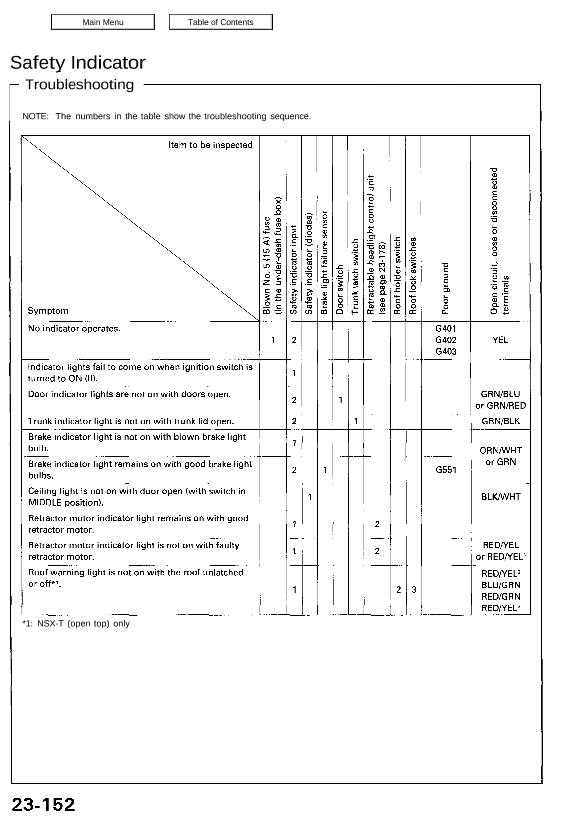
Safety Indicator *1: NSX-T (open top) only Troubleshooting NOTE: The numbers in the table show the troubleshooting sequence. Main Menu Table of Contents Safety Indicator — Troubleshooting NOTE: The numbers in the table show the troubleshooting sequence. Item to be inspected E ≣ 3: Ê š â A ↼ ‘E 3 8 g З 8 […]
Categories
nsxb23249b.pdf
Switch Test SRS components are located in this area. Review the SRS component locations, precautions, and procedures in the SRS (section 24) before performing repairs or ser- vice. 1. Disconnect the battery negative cable, then discon- nect the positive cable. 2. Make sure the wheels are turned straight ahead. 3. Remove the dashboard lower cover. […]
Categories
nsxd23318a.pdf
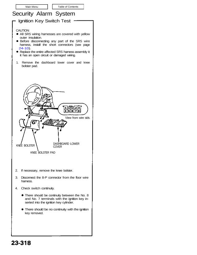
Security Alarm System Ignition Key Switch Test CAUTION: All SRS wiring harnesses are covered with yellow outer insulation. Before disconnecting any part of the SRS wire harness, install the short connectors (see page 24-10). Replace the entire affected SRS harness assembly it it has an open circuit or damaged wiring. 1. Remove the dashboard lower […]