Security Alarm System
Ignition Key Switch Test
CAUTION:
All SRS wiring harnesses are covered with yellow
outer insulation.
Before disconnecting any part of the SRS wire
harness, install the short connectors (see page
24-10).
Replace the entire affected SRS harness assembly it
it has an open circuit or damaged wiring.
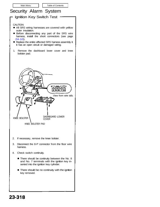
1. Remove the dashboard lower cover and knee
bolster pad.
DASHBOARD LOWER
COVER
2. If necessary, remove the knee bolster.
3. Disconnect the 8-P connector from the floor wire
harness.
4. Check switch continuity.
There should be continuity between the No. 8
and No. 7 terminals with the ignition key in-
serted into the ignition key cylinder.
There should be no continuity with the ignition
key removed.
KNEE BOLSTER
KNEE BOLSTER PAD
View from wire sids.
Ignition Key Switch Test
CAUTION:
All SRS wiring harnesses are covered with yellow
outer insulation.
Before disconnecting any part of the SRS wire
harness, install the short connectors (see page
24-10).
Replace the entire affected SRS harness assembly it
it has an open circuit or damaged wiring.
1. Remove the dashboard lower cover and knee
bolster pad.
DASHBOARD LOWER
COVER
2. If necessary, remove the knee bolster.
3. Disconnect the 8-P connector from the floor wire
harness.
4. Check switch continuity.
There should be continuity between the No. 8
and No. 7 terminals with the ignition key in-
serted into the ignition key cylinder.
There should be no continuity with the ignition
key removed.
KNEE BOLSTER
KNEE BOLSTER PAD
View from wire sids.