Category: Electrical
Categories
nsxb23084a.pdf
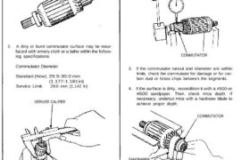
Starting System Armature Inspection and Test 1. Inspect the armature for wear or damage due to contact with the field coil magnets. Inspect for damage. 2. A dirty or burnt commutator surface may be resur- faced with emery cloth or a lathe within the follow- ing specifications. Commutator Diameter Standard (New): 29.9-30.0 mm (1.177-1.181 in) […]
Categories
nsxb23164a.pdf
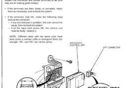
Integrated Control Unit Input Test SRS components are located in this area. Review the SRS component locations, precautions, and procedures in the SRS section 24 before performing repairs or ser- vice. Remove the left kick panel cover, and the relay holder from its bracket, then disconnect the 16-P connector from the integrated control unit. Remove […]
Categories
nsxb23068a.pdf
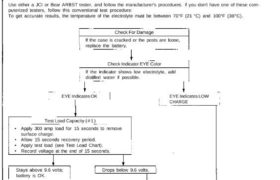
Battery Test • Battery fluid (electrolyte) contains sulfuric acid. It may cause severe burns if it gets on your skin or in your eyes. Wear protective clothing and a face shield. — If electrolyte gets on your skin or clothes, rinse it off with water immediately. — If electrolyte gets in your eyes, flush it […]
Categories
nsxb23076a.pdf
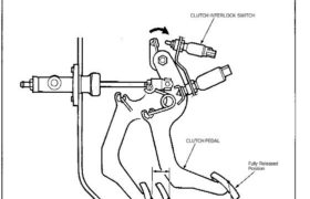
Starting System Description Starter Interlock System (M/T): The starter interlock system prevents the engine from starting unless the clutch pedal is fully depressed. The clutch interlock switch turns on at the position where the clutch disengages: 1 5 — 20 mm (0.59 — 0.79 in) from fully depressed position. NOTE: A full stroke of the […]
Categories
nsxd23288a.pdf
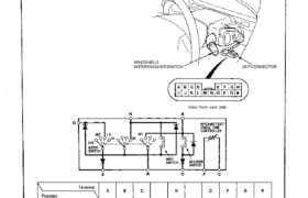
Wipers/Washers Windshield Wiper/Washer Switch Test 1. Remove the dashboard lower cover (see page 23-126). 2. Disconnect the 18-P connector from the floor wire harness. 3. Check for continuity between the terminals in each switch position according to the table. 18-P CONNECTOR WINDSHIELD WIPER/WASHER SWITCH View from wire side Attachments nsxd23288a (151 kB)
Categories
nsxb23208a.pdf
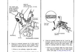
G551 ’93-’96 Models )G551 ’93-’96 Models) Back-up Lights Test Manual Transmission: 1. If only one back-up right does not go on, check that bulb in the taillight. 2. If neither back-up light goes on, check the No. 5 (15 A) fuse in the under-dash fuse box. 3. If the fuse and bulbs are OK, disconnect […]
Categories
nsxb23153a.pdf
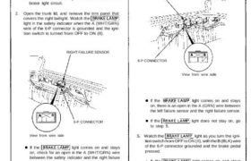
Brake Light Failure Sensor Test 1. First make sure the brake lights come on when the brake pedal is pressed. • If all the brake lights come on, go to step 2. • If one of the brake lights does not come on, check whether the bulb is blown. If the bulb is OK, go […]
Categories
nsxe23190a.pdf
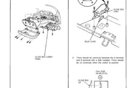
Glove Box Light Replacement/Test 1. Remove the glove box lower panel. 2. Remove the 8 screws then pull out the glove box. 3. Disconnect the 2-P connectors then remove the glove box. GLOVE BOX LOWER PANEL 4. Remove the 2 screws from the glove box light. GLOVE BOX LIGHT BULB (3.4W) 5. There should be […]
Categories
nsxb23188a.pdf
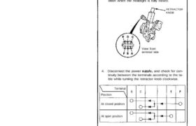
Lighting System Retractor Motor Test 1. Remove the retractor motor. 2. Test the motor by connecting battery power to the A terminal and ground to the D terminal. The motor should run continuously. 3. If the motor does not run or fails to run smoothly, replace it. NOTE: The illustration shows the motor in the […]
Categories
nsxb23308a.pdf
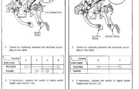
Cruise Control Brake Switch Test 1. Disconnect the 4-P connector from the switch. BRAKE SWITCH 4-P CONNECTOR BRAKE PEDAL 2. Check for continuity between the terminals accor- ding to the table. 3. If necessary, replace the switch or adjust pedal height (see section 19). Clutch Switch Test 1. Disconnect the 3-P connector from the switch. […]