Starting System
Armature Inspection and Test
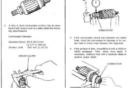
1. Inspect the armature for wear or damage due to
contact with the field coil magnets.
Inspect for
damage.
2. A dirty or burnt commutator surface may be resur-
faced with emery cloth or a lathe within the follow-
ing specifications.
Commutator Diameter
Standard (New): 29.9-30.0 mm
(1.177-1.181 in)
Service Limit: 29.0 mm (1.142 in)
VERNIER CALIPER
COMMUTATOR
Commutator Runout
Standard (New): 0—0.02 mm (0-0.0008 in)
Service Limit: 0.05 mm (0.002 in)
DIAL
INDICATOR
COMMUTATOR
3. If the commutator runout and diameter are within
limits, check the commutator for damage or for car-
bon dust or brass chips between the segments.
4. If the surface is dirty, recondition it with a #500 or
#600 sandpaper. Then, check mica depth. If
necessary, undercut mica with a hacksaw blade to
achieve proper depth.
COMMUTATOR
SANDPAPER
MICA DEPTH
Commutator Mica Depth
Standard (New): 0.5-0.8 mm (0.02-0.03 in)
Service Limit: 0.2 mm (0.008 in)
Armature Inspection and Test
1. Inspect the armature for wear or damage due to
contact with the field coil magnets.
Inspect for
damage.
2. A dirty or burnt commutator surface may be resur-
faced with emery cloth or a lathe within the follow-
ing specifications.
Commutator Diameter
Standard (New): 29.9-30.0 mm
(1.177-1.181 in)
Service Limit: 29.0 mm (1.142 in)
VERNIER CALIPER
COMMUTATOR
Commutator Runout
Standard (New): 0—0.02 mm (0-0.0008 in)
Service Limit: 0.05 mm (0.002 in)
DIAL
INDICATOR
COMMUTATOR
3. If the commutator runout and diameter are within
limits, check the commutator for damage or for car-
bon dust or brass chips between the segments.
4. If the surface is dirty, recondition it with a #500 or
#600 sandpaper. Then, check mica depth. If
necessary, undercut mica with a hacksaw blade to
achieve proper depth.
COMMUTATOR
SANDPAPER
MICA DEPTH
Commutator Mica Depth
Standard (New): 0.5-0.8 mm (0.02-0.03 in)
Service Limit: 0.2 mm (0.008 in)
5. Check for continuity between the segments of the
commutator. If an open circuit exists between any
segments, replace the armature.
COMMUTATOR
SEGMENT
6. Place the armature on an armature tester. Hold a
hacksaw blade on the armature core.
ARMATURE TESTER HACKSAW BLADE
ARMATURE
If the blade is attracted to the core or vibrates while
the core is turned, the armature is shorted. Replace
the armature.
7. With an ohmmeter, check that no continuity exists
between the commutator and armature coil core,
and between the commutator and armature shaft.
If continuity exists, replace the armature.
SHAFT COIL CORE COMMUTATOR