Categories
Electrical

nsxd23283a.pdf

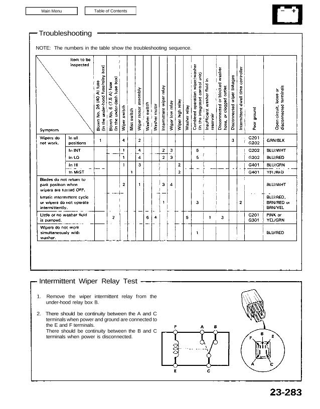
Troubleshooting NOTE: The numbers in the table show the troubleshooting sequence. Intermittent Wiper Relay Test 1. Remove the wiper intermittent relay from the under-hood relay box B. 2. There should be continuity between the A and C terminals when power and ground are connected to the E and F terminals. There should be continuity between […]

Categories
Electrical

nsxb23325a.pdf

Engine Compartment Lid Switch Test 1. Open the engine compartment lid. 2. Disconnect the 2-P connector from the engine compartment lid switch. 3. Check continuity at the switch connector terminals. • There should be continuity between the terminals with the lever released (lid open). • There should be no continuity with the lever pushed down […]

Categories
Electrical

nsxb23197a.pdf

Rear Side Marker Lights Replacement 1. Carefully pry the rear side marker light out of the rear fender. Be careful not to damage the rear parking light or the rear fender. Pry out here. REAR SIDE MARKER LIGHT REAR BUMPER PROTECTIVE CLOTH 2. Disconnect the 2-P connector from the rear side mar- ker light. SOCKET […]

Categories
Steering

nsxb17045a.pdf

Steering Wheel Removal Airbag Removal Store a removed airbag assembly with the pad surface up. If the airbag is improperly stored face down, accidental deployment could propel the unit with enough force to cause serious injury. NOTE: Before removing the steering wheel, make sure the front wheels are straight ahead. SRS components are located in […]

Categories
Fuel & Emissions

nsxd11090a.pdf

Idle Control System Troubleshooting Flowchart Air Conditioning Signal This signals the ECM when there is a demand for cooling from the air conditioning system. Inspection of Air Condition- ing Signal. Connect the test harness be- tween the ECM and connector. Disconnect “C” connector from the engine wire harness only, not the ECM (see page 11-37). […]

Categories
Electrical

nsxe23307a.pdf

Troubleshooting NOTE: The numbers in the table show the troubleshooting sequence. Main Menu Table of Contents Troubleshooting NOTE: The numbers in the table show the troubleshooting sequence. u x , Item to be inspected Ё 5.8 a ∖ f, 5 E >~ IJ w x .4: с u ∾ ⊏ ‘n w в ï: ∶≖ […]

Categories
Automatic Transmission

nsxd14050a.pdf

Troubleshooting Procedures When the Transmission Control Module (TCM) senses an abnormality in the input or output systems, the indicator light in the gauge assembly will blink. However, when the Service Check Connector (located to the lower right of the glove compartment) is connected with a jumper wire, the indicator light will blink the Diagnostic Trouble […]

Categories
Uncategorized

nsx14indxa.pdf

Automatic Transmission (’91−’94 Models) Special Tools 14−2. . . . . . . . . . . . . . . Description General Operation 14−3. . . . . . . Clutches 14−6. . . . . . . . . . . . . . . . Power Flow 14−9. . . . . […]

Categories
Electrical

nsxb23261a.pdf

Power Door Locks Component Location Index UNDER-HOOD FUSE/RELAY BOX Located at right side of front compartment IGNITION KEY SWITCH Test, page 23-171 POWER DOOR LOCK CONTROL UNIT Input Test, page 23-264 PASSENGER’S DOOR SWITCH Test, page 23-204 DRIVER’S DOOR LOCK SWITCH Test, page 23-268 DRIVER’S DOOR SWITCH Test, page 23-204 DRIVER’S DOOR LOCK ACTUATOR ASSEMBLY […]

Categories
Electrical

nsxb23213a.pdf

Side Marker/Turn Signal/Hazard Flasher System Component Location Index SRS components are located in this area. Review the SRS component locations, precautions, and procedures in the SRS section (24) before performing repairs or service. TURN SIGNAL INDICATOR LIGHTS (In the gauge assembly) Gauge Assembly, page 23-125 HAZARD WARNING SWITCH Removal, page 23-220 Test, page 23-221 HEADLIGHT […]