Idle Control System
Troubleshooting Flowchart Air Conditioning Signal
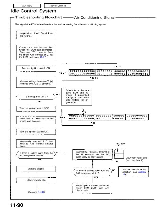
This signals the ECM when there is a demand for cooling from the air conditioning system.
Inspection of Air Condition-
ing Signal.
Connect the test harness be-
tween the ECM and connector.
Disconnect “C” connector from
the engine wire harness only, not
the ECM (see page 11-37).
Turn the ignition switch ON.
Measure voltage between C3 (+)
terminal and A26 (-) terminal.
Is there approx. 10 V?
Turn the ignition switch OFF.
Reconnect “C” connector to the
engine wire harness.
Turn the ignition switch ON.
Momentarily connect A15 ter-
minal to A26 terminal several
times.
Is there a clicking noise from the
A/C compressor clutch?
Start the engine.
Blower switch ON.
(To page 11-91)
Repair open in RED/BLU wire be-
tween ECM (A15) and A/C
clutch relay.
Is there a clicking noise from the
A/C compressor clutch?
Connect the RED/BLU terminal of
the 4P connector on the A/C
clutch relay to body ground. View from relay side
(sub relay box A)
RED/BLU
See air conditioner in-
spection (see section
22).
Substitute a known-
good ECM and re-
check. If prescribed
voltage is now avail-
able, replace the ori-
ginal ECM.
Troubleshooting Flowchart Air Conditioning Signal
This signals the ECM when there is a demand for cooling from the air conditioning system.
Inspection of Air Condition-
ing Signal.
Connect the test harness be-
tween the ECM and connector.
Disconnect “C” connector from
the engine wire harness only, not
the ECM (see page 11-37).
Turn the ignition switch ON.
Measure voltage between C3 (+)
terminal and A26 (-) terminal.
Is there approx. 10 V?
Turn the ignition switch OFF.
Reconnect “C” connector to the
engine wire harness.
Turn the ignition switch ON.
Momentarily connect A15 ter-
minal to A26 terminal several
times.
Is there a clicking noise from the
A/C compressor clutch?
Start the engine.
Blower switch ON.
(To page 11-91)
Repair open in RED/BLU wire be-
tween ECM (A15) and A/C
clutch relay.
Is there a clicking noise from the
A/C compressor clutch?
Connect the RED/BLU terminal of
the 4P connector on the A/C
clutch relay to body ground. View from relay side
(sub relay box A)
RED/BLU
See air conditioner in-
spection (see section
22).
Substitute a known-
good ECM and re-
check. If prescribed
voltage is now avail-
able, replace the ori-
ginal ECM.
(From page 11-90)
A/C switch ON.
Does A/C operate ?
Air conditioning signal is OK.
Is voltage less than 1.0 V?
Measure voltage between C3
( + ) terminal and A26 (-) ter-
minal.
Substitute a known-good ECM
and recheck. If symptom/indica-
tion goes away, replace the orig-
inal ECM.
Repair open in BLU/
BLK wire between ECM
(C3) and A/C switch.