Categories
Steering

nsxb17020a.pdf

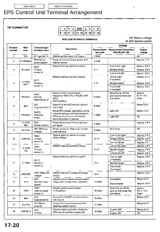
EPS Control Unit Terminal Arrangement Main Menu Table of Contents EPS Control Unit Terminal Arrangement l 1 ↽ −−∙ 8P CONNECTOR ,I 2 3 4 5 6 7 8 9 1011 121314515161718 WIRE SIDE OF FEMALE TERMINALS VB’ Batteer VD|t_age IG SW: lgnmon swnch Voltage Terminal Wire Terminal sign! . . „umher colo, Terminal „ma […]

Categories
Body

nsxd20055a.pdf

Replacement SRS wire harnesses are routed near the dashboard and steering column. CAUTION: All SRS wiring harnesses are covered with yellow outer insulation. Before disconnecting any part of the SRS wire harness, install the short connectors (see page 23-328). Replace the entire affected SRS harness assem- bly if it has an open circuit or damaged […]

Categories
Brakes & ABS

nsxe19044a.pdf

Troubleshooting Anti-lock Brake System Indicator Light Temporary Driving Conditions: 1. The anti-lock brake system indicator light will come on and the control unit memorizes the problem under certain conditions. NOTE: Problem codes are explained on pages 19 – 46. The tire(s) adhesion is lost due to excessive cor- nering speed. Problem codes: 5, 5-4, 5-8. […]

Categories
General Info

nsxa01005a.pdf

Warning/Caution Label Locations SRS CAUTION LABELS: Refer to page 1-6 FROZEN BATTERY CAUTION AIR CONDITIONING R-134a CAUTION (U.S.A. only) ENGINE COOLANT CAUTION • PRECAUTION ABS CAUTION ABS and BRAKE FLUID CAUTION RETRACTABLE HEADLIGHT CAUTION EMISSION CONTROL INFORMATION and VACUUM HOSE ROUTING DIAGRAM BATTERY CAUTION RADIATOR BLEED PLUG CAUTION EXPANSION TANK CAP CAUTION SPARK PLUG CAUTION […]

Categories
General Info

nsxb01011a.pdf

Safety Stands CAUTION: Place a rubber pad between the safety stand platforms and the car’s front and rear support points to avoid damaging the car. The safety stand platforms must contact the car’s support points only; they must not come in contact with any other part of the car. SAFETY STANDS SUPPORT POINTS RUBBER PADS […]

Categories
Intake Manifold & Exhaust System

nsxb09002a.pdf

Special Tools Ref. No. Tool Number Description Qty Page Reference 9-4(’91-’93) or (’94-’96), 5 (’94-’96), O 2 Sensor Socket Wrench07LAA – PT50101 1 Main Menu Table of Contents Special Tools Ref, N0. | Tool Number I Description Qty Page Reference (D I 07LAA — PT50101 ì 02 Sensor Socket Wrench l 94(‘91—93) or (’94—’96), 5 […]

Categories
Electrical

nsxb23241a.pdf

Power Antenna Motor Test 1. Open the trunk lid and remove the side trim panel. 2. Disconnect the 4-P connector from the motor and check power to the motor at the connector terminals: • There should be battery voltage between the WHT/BLU (+) and BLK (-) terminals all the time. • There should be battery […]

Categories
General Info

nsxb01009a.pdf

Lift and Support Points Lift CAUTION: If ground clearance is inadequate to clear the shop lift, either: — Install rubber spacers on the coil springs to raise the car. Use the floor jack procedures to raise the car (page 1-10). or — Remove the chin spoiler. or — If you need even more clearance, install […]

Categories
Electrical

nsxb23293a.pdf

Windshield Wiper Motor Test 1. Open the hood, and remove the cap nuts and the wiper arms. Don’t let the wiper arms hit the hood. WIPER ARM WINDSHIELD LOWER MOLDING HOOD SEAL AIR SCOOP 2. Remove the windshield lower molding, hood seal and air scoop by prying off the trim clips and removing the screws. […]

Categories
Electrical

nsxb23005a.pdf

Five-step Troubleshooting 1. Verify The Complaint Turn on all the components in the problem circuit to verify the customer complaint. Note the symp- toms. Do not begin disassembly or testing until you have narrowed down the problem area. 2. Analyze The Schematic Look up the schematic for the problem circuit. Determine how the circuit is […]