EPS Control Unit Terminal Arrangement
Main Menu Table of Contents
EPS Control Unit Terminal Arrangement
l
1 ↽ −−∙
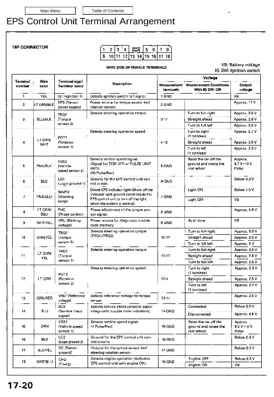
8P CONNECTOR ,I 2 3 4 5 6 7 8
9 1011 121314515161718
WIRE SIDE OF FEMALE TERMINALS VB’ Batteer VD|t_age
IG SW: lgnmon swnch
Voltage
Terminal Wire Terminal sign! . .
„umher colo, Terminal „ma De’mmw“ Measurement Measurement Conditions Output
terminals With IG SW: ON voltage
1 YEL lG1 (Ignition 1) Detects ignition switch IGl signal. 1-GND VB
2 LT GRN/ELK SPS (Sensor Power source tortorque sensor and 2_GND Approx. 11 V
power supply) rotation sensor.
TR02 Detects steering operation torque. Turn to full right Approx. 2.6 V
3 BLU/ELK [Torque 3—17 Straight ahead Approx. 2.8V
≘⊜⊓≤∘↾ ≀⇂ ⊤⋯⊓ to full left Approx. 3.0 v
Detects steering operation speed. Turn to right Approx. 2.7 V
(1 turn/sec)
LT GRN/ ROT] . .
4 WHT (Rotation 4-12 Straight ahead Approx. 2.5 V
sensor ∥ Turn to left Approx. 2.3 V
(1 turn/sec)
V552 Detects vehicle speed signal. Raise the car of! the Approx.
5 PNK/BLK (vehicle (Signal for TCM (AT) or PULSE UNIT 5_GND ground and rotate the 4.7 v»o V
speed sensor 2) (MTJ) rearwheel Pulse
(50 Pulse/Rev)
6 ELK LG1 ‘ Ground for the EFS control unit conw депо Below 03 V
(Logic ground 1) trol circuit.
Drives EPS indicator light (Shuts off the Light ON Below 1.5 V
WARN indicator light ground circuit inside the
7 PNK/BLU (wammg EPS control unit to turn off the light ?GND Light он: v5
lamp) .
when the system is normal).
LT GRN/ PHC Phase adjustment of the torque sen- Approx. 4.5 V
8 . 8-GND
RED (Phase control) sor Signal.
9 WHT/YEL VBU (Back-up Power source for diagnostic trouble SAGND At all time VB
voltage) code memory.
⊺∏≺⊐⋮ Detects steering operation torque Turn to full right Approx. 5.0 V
10 GRN/VEL (Torque ≺⊺⊓∘↿≁⊺∏∘≵⋟⋅ 10-17 Straight ahead Approx. 2.5 v
Sensor 3) Turn to full left Approx. 0 V
Tam Detects steering operation torque. Turn to full right Approx. 3.0 V
11 LTV‘ËÎN/ (Torque 11-17 Straight ahead Approx. 2.8 V
sensor 1) Turn to full left Approx. 2.6 V
Detects steering operation speed. Turn to right Approx. 2.3 V
HOT; (1 turn/sec)
12 LT GRN (Rotation 12-4 Straight ahead Approx. 2.5 V
Sensor 2) Turn to left Approx. 2.7 V
(1 turn/sec)
13 GRN/RED VFlEF (Reference Detects reference voltage for torque 13’17 Approx. 2.5 V
voltagel senser.
SCS Detects service check conector signal Connected Below 0.3 V
14 BLU (Service check (diagnostic trouble code indication). 14~GND _
signal) Disconnected Approx. 4.8 V
VSS1 Detects vehicle speed signal. Raise the car off the Approx.
15 ORN (Vehicle speed (4 Pulse/Rev) 15—GND ground and rotate the 5.0 ∨∙⊳∘ ∨
sensor 1) rear wheel Pulse
LGZ Ground for the EPS control unit con» Below 0.3 V
16 ELK (Logicground 2) trol circuits. .Is-GND
∏ ELK/YEL SG (Sensor Ground for the torque sensor and „_GND Below 0.3 V
ground) steering rotation sensor.
WHT LU CHG Detects engine operation (Activates Engine: OFF Below 0.3 V
18 ’B (Charg) EPS control unit with engine ON). ”GND ⊑⊓⊊⋮∩⊜∶ ∘∣∖⇃ VB
17-20
3P CONNECTOR (LEFT SIDE)
WIRE SIDE OF FEMALE TERMINALS
VB: Battery voltage
IG SW: Ignition switch
3P CONNECTOR (RIGHT SIDE)
WIRE SIDE OF FEMALE TERMINALS
VB: Battery voltage
IG SW: Ignition switch
6P CONNECTOR
WIRE SIDE OF FEMALE TERMINALS
4P CONNECTOR
WIRE SIDE OF FEMALE TERMINALS
PULSE UNIT 7P CONNECTOR (MT)
WIRE SIDE OF FEMALE TERMINALS
Main Menu Table of Contents
EPS Control Unit Terminal Arrangement
l
1 ↽ −−∙
8P CONNECTOR ,I 2 3 4 5 6 7 8
9 1011 121314515161718
WIRE SIDE OF FEMALE TERMINALS VB’ Batteer VD|t_age
IG SW: lgnmon swnch
Voltage
Terminal Wire Terminal sign! . .
„umher colo, Terminal „ma De’mmw“ Measurement Measurement Conditions Output
terminals With IG SW: ON voltage
1 YEL lG1 (Ignition 1) Detects ignition switch IGl signal. 1-GND VB
2 LT GRN/ELK SPS (Sensor Power source tortorque sensor and 2_GND Approx. 11 V
power supply) rotation sensor.
TR02 Detects steering operation torque. Turn to full right Approx. 2.6 V
3 BLU/ELK [Torque 3—17 Straight ahead Approx. 2.8V
≘⊜⊓≤∘↾ ≀⇂ ⊤⋯⊓ to full left Approx. 3.0 v
Detects steering operation speed. Turn to right Approx. 2.7 V
(1 turn/sec)
LT GRN/ ROT] . .
4 WHT (Rotation 4-12 Straight ahead Approx. 2.5 V
sensor ∥ Turn to left Approx. 2.3 V
(1 turn/sec)
V552 Detects vehicle speed signal. Raise the car of! the Approx.
5 PNK/BLK (vehicle (Signal for TCM (AT) or PULSE UNIT 5_GND ground and rotate the 4.7 v»o V
speed sensor 2) (MTJ) rearwheel Pulse
(50 Pulse/Rev)
6 ELK LG1 ‘ Ground for the EFS control unit conw депо Below 03 V
(Logic ground 1) trol circuit.
Drives EPS indicator light (Shuts off the Light ON Below 1.5 V
WARN indicator light ground circuit inside the
7 PNK/BLU (wammg EPS control unit to turn off the light ?GND Light он: v5
lamp) .
when the system is normal).
LT GRN/ PHC Phase adjustment of the torque sen- Approx. 4.5 V
8 . 8-GND
RED (Phase control) sor Signal.
9 WHT/YEL VBU (Back-up Power source for diagnostic trouble SAGND At all time VB
voltage) code memory.
⊺∏≺⊐⋮ Detects steering operation torque Turn to full right Approx. 5.0 V
10 GRN/VEL (Torque ≺⊺⊓∘↿≁⊺∏∘≵⋟⋅ 10-17 Straight ahead Approx. 2.5 v
Sensor 3) Turn to full left Approx. 0 V
Tam Detects steering operation torque. Turn to full right Approx. 3.0 V
11 LTV‘ËÎN/ (Torque 11-17 Straight ahead Approx. 2.8 V
sensor 1) Turn to full left Approx. 2.6 V
Detects steering operation speed. Turn to right Approx. 2.3 V
HOT; (1 turn/sec)
12 LT GRN (Rotation 12-4 Straight ahead Approx. 2.5 V
Sensor 2) Turn to left Approx. 2.7 V
(1 turn/sec)
13 GRN/RED VFlEF (Reference Detects reference voltage for torque 13’17 Approx. 2.5 V
voltagel senser.
SCS Detects service check conector signal Connected Below 0.3 V
14 BLU (Service check (diagnostic trouble code indication). 14~GND _
signal) Disconnected Approx. 4.8 V
VSS1 Detects vehicle speed signal. Raise the car off the Approx.
15 ORN (Vehicle speed (4 Pulse/Rev) 15—GND ground and rotate the 5.0 ∨∙⊳∘ ∨
sensor 1) rear wheel Pulse
LGZ Ground for the EPS control unit con» Below 0.3 V
16 ELK (Logicground 2) trol circuits. .Is-GND
∏ ELK/YEL SG (Sensor Ground for the torque sensor and „_GND Below 0.3 V
ground) steering rotation sensor.
WHT LU CHG Detects engine operation (Activates Engine: OFF Below 0.3 V
18 ’B (Charg) EPS control unit with engine ON). ”GND ⊑⊓⊊⋮∩⊜∶ ∘∣∖⇃ VB
17-20
3P CONNECTOR (LEFT SIDE)
WIRE SIDE OF FEMALE TERMINALS
VB: Battery voltage
IG SW: Ignition switch
3P CONNECTOR (RIGHT SIDE)
WIRE SIDE OF FEMALE TERMINALS
VB: Battery voltage
IG SW: Ignition switch
6P CONNECTOR
WIRE SIDE OF FEMALE TERMINALS
4P CONNECTOR
WIRE SIDE OF FEMALE TERMINALS
PULSE UNIT 7P CONNECTOR (MT)
WIRE SIDE OF FEMALE TERMINALS