Categories
Fuel & Emissions

nsxb11024a.pdf

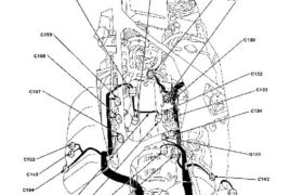
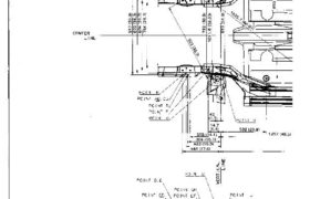
System Description System Connectors [Engine Compartment (Right Side)] Main Menu Table of Contents System Description System Connectors [Engine Compartment (Right Side)] C173 c159 c158 c132 c157 c133 c134 G101 c152 c153 c142 c154 KNOCK SENSOR c172 c145 HARNESS C156 C155 C151 C148 ENGINE WIRE HARNESS 11—24 NOTE: • Different wires with the same color have […]

Categories
Body

nsxb20033a.pdf

Rear Hatch Glass Removal CAUTION: • Use covers to avoid damaging the body. • Wear gloves to remove and install the glass. • Do not damage the defroster grid lines. • Take care not scratch or score the molding. 1. Remove the rear hatch assembly from the body (see page 20-64). 2. Using an awl, […]

Categories
Electrical

nsxb23246a.pdf

Horns Component Location Index SRS components are located in this area. Review the SRS component locations, precautions, and procedures in the SRS section (24) before performing repairs or ser- vice. HORN RELAY Test, page 23-249 UNDER-HOOD RELAY BOX A CABLE REEL Test, page 23-250 HORN SWITCH Test, page 23-249 Overhaul, section 17 SECURITY HORN Test, […]

Categories
Brakes & ABS

nsxb19004a.pdf

Pedal Height Adjustment 1. Loosen the brake switch locknut, and back off the brake switch until it is no longer touching the brake pedal. 2. Loosen the pushrod locknut, and screw the pushrod in or out with pliers until the standard pedal height from the floor is 218 mm (8.6 in). After adjust- ment, tighten […]

Categories
Body

nsxb20074a.pdf

Frame Repair Chart Unit: mm (in) Mam Menu Table of Contents Frame Repair Chart Unit: mm (in) POINT EF PDINT GH i POINT ⊟⊇↲↽∼⊺ E шт ——7 E’ng ∁ ∖ ≸⊃⊇⊓∖⊔ A I mis:. а: зава a N O Q Ч N’ v- ” C) ¡n w CENTER °’ “’ °° ↾∖ ” LINE › […]

Categories
Electrical

nsxd23010a.pdf

Relay and Control Unit Locations Rear Bulkhead FAN CONTROL UNIT ECM TCS FAIL-SAFE RELAY Wire colors: YEL, and LT GRN/BLK TRANSMISSION CONTROL MODULE (TCM) DASH LIGHTS BRIGHTNESS CONTROL UNIT TCS CONTROL UNIT GRN/RED, RED/BLK, RETRACTABLE HEADLIGHT CONTROL UNIT INTERLOCK CONTROL UNIT (A/T) FUEL PUMP RELAY Wire colors: YEL, RED, BLK/YEL, and BLK/RED 23-11 Attachments nsxd23010a […]

Categories
Body

nsxb20073a.pdf

Rear Sub-frame Sub-frame torque value specifications: LEFT REAR BRACKET RIGHT REAR BRACKET 10 x 1.25 mm 60 N-m (6.0 kg-m. 43 Ib-ft) 10 x 1.25 mm 60 N-m (6.0 kg-m. 43 Ib-ft) FRONT BEAM 10 x 1.25 mm 60 N-m (6.0 kg-m, 43 Ib-ft) 10 x 1.25 mm 60 N-m (6.0 kg-m, 43 Ib-ft) CENTER […]

Categories
Brakes & ABS

nsxb19072a.pdf

Pulsers/Sensors Front Sensor Replacement NOTE: • Be careful when installing the sensors to avoid twisting the wires. • After sensor replacement confirm proper opera- tion (see page 19-43). CORROSION RESISTANT BOLT 6 x 1.0 mm 10 N-m (1.0 kg-m. 7 Ib-ft) 6 x 1.0 mm 10 N-m (1.0 kg-m, 7 Ib-ft) 8 x 1.25 mm […]

Categories
Brakes & ABS

nsxe19063a.pdf

Modulator/Solenoid Unit Index/Torque CAUTION: Do not damage the brake pipes when removing the spare tire and modulator/solenoid unit. Do not spill brake fluid on the car; it may damage the paint; if brake fluid does contact the paint, wash it off immediate- ly with water. CORROSION RESISTANT BOLT 19 N·m (1.9 kg-m. 14 Ib-ft) MODULATOR/SOLENOID […]

Categories
Steering

nsxd17031a.pdf

System Description Electrical Power Steering (EPS) Outline The NSX uses an electric motor-driven power steering, which possesses the characteristics best suited for a mid engine automobile. This system is a power-assisted steering device, with a motor inside the steering gearbox driven by the EPS control unit and power unit. Its distinctive features are described below: […]