A/T Gear Position Indicator
CAUTION:
• All SRS wiring harnesses are covered with yellow out-
er insulation.
• Before disconnecting any part of the SRS wire har-
ness, install the short connectors (see page 24-10 (’93-’96))
• Replace the entire affected SRS harness assembly if
it has an open circuit or damaged wiring.
• After installing the gauge assembly, recheck the oper-
ation of the SRS Indicator light.
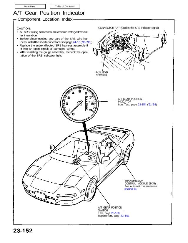
CONNECTOR “A” (Carrios the SRS Indicator signal)
SRS MAIN
HARNESS
A/T GEAR POSITION
INDICATOR
Input Test, page 23-154 (’91-’93)
TRANSMISSION
CONTROL MODULE (TCM)
See Automatic transmission
section 14
AfT GEAR POSITION
SWITCH
Test, page 23-160
Replacement, page 23-161
Component Location Index
CAUTION:
• All SRS wiring harnesses are covered with yellow out-
er insulation.
• Before disconnecting any part of the SRS wire har-
ness, install the short connectors (see page 24-10 (’93-’96))
• Replace the entire affected SRS harness assembly if
it has an open circuit or damaged wiring.
• After installing the gauge assembly, recheck the oper-
ation of the SRS Indicator light.
CONNECTOR “A” (Carrios the SRS Indicator signal)
SRS MAIN
HARNESS
A/T GEAR POSITION
INDICATOR
Input Test, page 23-154 (’91-’93)
TRANSMISSION
CONTROL MODULE (TCM)
See Automatic transmission
section 14
AfT GEAR POSITION
SWITCH
Test, page 23-160
Replacement, page 23-161
Component Location Index