Installation
Before installing the crankshaft, apply a coat of
engine oil to the main bearings and rod
bearings.
1. Insert bearing halves in the engine block and con-
necting rods.
2. Lower the crankshaft into the block.
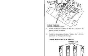
3. Install the thrust washers on the No. 3 journal. Oil
thrust washer surfaces.
4. Install the bearings and caps. Tighten 9 x 1.25 mm
cap bolts to the specified torque.
NOTE:
• Guide the piston carefully to prevent damage.
• Fit long rubber hoses (about 30 cm long) to con-
necting rod bolts to protect the crankshaft.
• Install the pistons after setting the crankshaft to
BDC for each cylinder.
CORRECT INCORRECT
RUBBER HOSES
9 x 0.75 mm
20 N-m (2.0 kg-m, 14 Ib-ft)
after turn to 95°
MARK
• Line up the marks when installing connecting
rod cap.
5. Check the rod bearing clearance with plastigage
(see page 7-7), then torque the connecting rod cap
nuts.
NOTE: Reference numbers on connecting rods are
for big-end bore tolerance and do NOT indicate the
position of piston in engine.
CONNECTING ROD CAP NUT TORQUING
METHOD
1) Torque the connecting rod cap nut to 20 N-m
(2.0 kg-m, 14 Ib-ft) with a beam-type torque
wrench.
2) Install a torque angle gauge to the cap nut, then
turn the cap nut 95 degrees.
Snap-on
TA360 or
equivalent
BEARING CAP
WASHERS
Crankshaft
Installation
6. Install the bearing cap bridge, and tighten 11 x 1.5
mm bolts to the specified torque diagonally out-
ward from the center.
Torque 66 N-m (6.6 kg-m, 48 Ib-ft)
7. Tighten cap side bolts (10 x 1.25 mm) to the
specified torque.
Torque: 50 N-m (5.0 kg-m, 36 Ib-ft)
• Coat the bolt thread and seat surface with
engine oil.
NOTE: The shorter side bolts are for the front side.
BEARING CAP
BRIDGE CAP BRIDGE BOLT
11 x 1.5 mm
66 N-m (6.6 kg-m,
48 Ib-ft)
SIDE BOLT
10 x 1.25 mm
50 N-m (5.0 kg-m,
36 Ib-ft) CAP BOLT9 x 1.25 mm
40 N-m (4.0 kg-m,
29 Ib-ft)
8. Apply liquid gasket to the block mating surface of
the left side cover and oil pump case, and install
them on the engine block.
NOTE: The seal surface on the block should be
dry. Apply a light coat of oil to the crankshaft and
to the lip of seal.
LEFT SIDE:
Apply liquid
gasket to block
mating surface.
LEFT SIDE COVER
SPECIAL BOLTS
6 x 1.0 mm
12 N-m (1.2 kg-m,
9 Ib-ft)
Replace.
DOWEL PIN
BEARING CAP BOLTS TORQUE SEQUENCE
6 x 1.0 mm
12 N-m (1.2 kg-m,
9 Ib-ft)
OIL PUMP
Apply liquid
gasket to block
mating surfaces.
SPECIAL BOLTS
6 x 1.0 mm
12 N-m (1.2 kg-m,
9 Ib-ft)
Replace.
SPECIAL BOLTS
8 x 1.25 mm
22 N-m (2.2 kg-m,
16 Ib-ft)
Replace.
NOTE:
• Use liquid gasket, Part No. 08718-0001.
• Check that the mating surfaces are clean and
dry before applying liquid gasket.
• Apply liquid gasket evenly, being careful to cover
all of the mating surface.
• To prevent leakage of oil, apply liquid gasket to
the inner threads of the bolt holes.
LEFT
SIDE COVER
Apply liquid gasket
along the broken line.
OIL PUMP
Apply liquid gasket
along the broken line.
• Do not install the parts if five minutes or more
have elapsed since applying liquid gasket.
Instead reapply liquid gasket after removing old
residue.
• After assembly, wait at least 20 minutes before
filling the engine with oil.
9. Install the oil pass pipe and joint.
10. Install the baffle plate.
11. Install the oil screen.
12. Install the oil pan (see page 8-10).
CAUTION: Whenever any crankshaft or connec-
ting rod bearing is replaced, after reassembly, run
the engine at idling speed until it reaches normal
operating temperature, then continue to run for ap-
proximately 15 minutes.
OIL PUMP SIDE:
6 x 1.0 mm
12 N-m (1.2 kg-m, 9 Ib-ft)
OIL SCREENBAFFLE PLATE
OIL PASS
PIPE