Category: Electrical
Categories
nsxb23158a.pdf
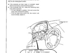
A/T Gear Position Indicator Indicator Input Test SRS components are located in this area. Review the SRS component locations, precautions, and procedures in the SRS section (24) before performing repairs or ser- vice. Remove the dashboard lower cover, dashboard lower pad and instrument panel. Disconnect the connector “A” 130-P) from the gauge assembly (see page […]
Categories
nsxd23177a.pdf
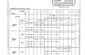
Combination Light /Turn Signal Switch Test 16-P CONNECTOR 1. Remove the dashboard lower cover and knee bolster pad. 2. If necessary, remove the knee bolster. 3. Disconnect the 16-P connector from the floor wire harness. 4. Check for continuity between the terminals, in each switch position according to the table. View from wire side Turn […]
Categories
nsxb23161a.pdf
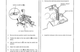
A/T Gear Position Switch Replacement SRS components are located in this area. Review the SRS component locations, precautions, and procedures in the SRS section (24) before performing repairs or ser- vice. 1. Remove the console, then disconnect the 12-P and 2-P connectors from the A/T gear position switch. SWITCH SLIDER (In ) PIN A/T GEAR […]
Categories
nsxb23078a.pdf
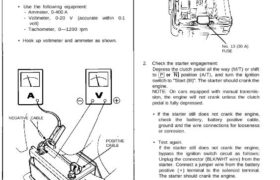
Starting System Starter Test NOTE: The air temperature must be between 59 and 100°F (15 and 38°C) before testing. Recommended Procedure: • Use a starter system tester. • Connect and operate the equipment in accor- dance with manufacturer’s instructions. Alternate Procedure: • Use the following equipment: – Ammeter, 0-400 A – Voltmeter, 0-20 V (accurate […]
Categories
nsxb23106a.pdf
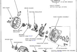
Charging System Alternator Overhaul NOTE: It is only necessary to separate the pulley, drive end housing and rotor when the front bearing needs replacement. Loosen the locknut with 10 mm and 22 mm wrenches to remove the pulley from the rotor. If necessary, use an impact wrench. TERMINAL INSULATOR PULLEY 22 mm BOX WRENCH 10 […]
Categories
nsxb23107a.pdf
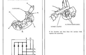
Rectifier Test NOTE: The diodes are designed to allow current to pass in one direction while blocking it in the opposite direction. Since the alternator rectifier is made up of eight diodes (four pairs), each diode must be tested for continuity in both directions with an ohmmeter that has diode checking capability; a total of […]
Categories
nsxb23110a.pdf
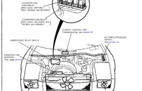
Radiator and Condenser Fan Controls Component Location Index RADIATOR FAN LOW RELAY Wire colors: WHT/BLU, YEL/BLK, RED and GRN/BLK RADIATOR FAN HIGH RELAY Wire colors: WHT/BLU BLK, YEL/BLK and BLU/RED CONDENSER FAN RELAY Wire colors: WHT/GRN, BLK YEL/BLK and ORN/BLU RIGHT CONDENSER FAN MOTOR Test, page 23-117 Replacement, see section 22 UNDER-HOOD RELAY BOX A […]
Categories
nsxd23274a.pdf
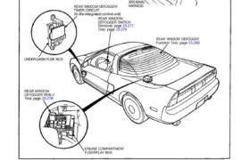
Rear Window Defogger Component Location Index CAUTION: All SRS wiring harnesses are covered with yellow outer insulation. Before disconnecting any part of the SRS wire harness, install the short connectors (see page 24-10). Replace the entire affected SRS harness assembly if it has an open circuit or damaged wiring. REAR WINDOW DEFOGGER TIMER CIRCUIT (In […]
Categories
nsxb23080a.pdf
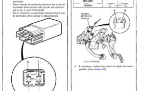
Starting System Starter Cut Relay Test 1. Remove the glove box (see section 20). 2. Disconnect the 4-P connector from the starter cut relay. (Wire colors of 4-P connector: BLK/GRN, BLK/ WHT, BLK/BLU and BLK/WHT) 3. Check continuity at the relay terminals. • There should be continuity between the C and D terminals. • There […]
Categories
nsxb23155a.pdf
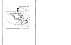
Roof Holder Switch Test 1. Open the rear hatch and engine cover. 2. Disconnect the 1- P connector from the roof holder switch. 3. There should be continuity between the A and B ter- minals with the switch released (roof not stored). 4. There should be no continuity with the switch pushed (roof stored). Roof […]