Categories
Electrical

nsxb23086a.pdf

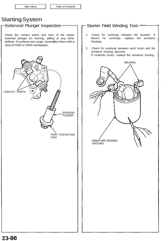
Starting System Solenoid Plunger Inspection Check the contact points and face of the starter solenoid plunger for burning, pitting or any other defects. If surfaces are rough, recondition them with a strip of #500 or #600 sandpaper. CONTACT POINTS SOLENOID PLUNGER POINT CONTACTING FACE Starter Field Winding Test 1. Check for continuity between the brushes. […]

Categories
Steering

nsxb17025a.pdf

Symptom-to-System Chart Diagnostic Trouble Code (DTC) 17-27 17-29 17-31 17-36 17-38 17-40 Initial diagnosis: Performed right after the engine starts until the EPS indicator light goes off. Regular diagnosis: Continuously performed (under some conditions) after the EPS indicator light goes off until the engine stops. Individual part/system diagnosis: Diagnoses a specific part/system under its operating […]

Categories
Electrical

nsxb23171a.pdf

Key-in Reminder System Ignition Key Switch Test NOTE: Refer to page 23-165 for the input test of key-in reminder, beeper circuit. When the ignition key is not removed, the key-in reminder in the integrated control unit senses ground through the closed ignition key switch. When you open the driver’s door, the reminder circuit senses ground […]

Categories
Manual Transmission

nsxb13023a.pdf

Mainshaft Assembly Index NOTE: The 3rd/4th and 5th synchro hubs are installed with a press. Prior to reassembling, clean all the parts in solvent, dry them, and apply lubricant to any contact surfaces. The 3rd/4th and 5th synchro hubs, however, should be installed with a press before lubricating them. 3RD/4TH SYNCHRO HUB SYNCHRO SPRING SYNCHRO […]

Categories
Manual Transmission

nsxb13029a.pdf

Countershaft Assembly Index NOTE: The 3rd, 4th and 5th gears are installed with a press. Prior to reassembling, clean all the parts in solvent, dry them, and apply lubricant to any contact surfaces. The 3rd, 4th and 5th gears should be installed without lubrication using a press. SYNCHRO SPRING SYNCHRO RING Inspection, page 13-35 1ST […]

Categories
Brakes & ABS

nsxb19046a.pdf

Troubleshooting Symptom-to-System Chart 19-47 19-50 19-71 19-71 19-51 19-52 19-53 19-71 19-57 19-55 19-59 Mam Menu Table of Contents Troubleshooting Symptom—to—System Chart DIAGNOSTIC TROlÍÊl-i’îfODE PROBLEMATIC AFFECTED OTHER COMPONENT/ PAGE PAGE COMPONENT MAIN sua- SYSTEM FRONT FRONT REAR REAR CODE CODE RIGHT LEFT RIGHT LEFT ABS [40Al fuse Hydraulic Motor relay 19-71 Ф- w Controlled _ […]

Categories
Automatic Transmission

nsxd14157a.pdf

Shift Cable Adjustment 1. Start the engine. Shift to reverse to see if the reverse gear engages. If not, refer to Trouble- shooting on pages 14-84 thru 14-87. 2. Stop the engine. 3. Raise the car (see section 1). 4. Shift the selector lever to position. 5. Remove the shift cable cover. 6. Remove the […]

Categories
Manual Transmission

nsxb13003a.pdf

Maintenance Transmission Oil NOTE: Check the oil at normal operating temperature (the cooling fan comes on), engine OFF, and the car on level ground. 1. Remove the oil filler plug, then check the level and condition of the oil. WASHER Replace. Proper Level. OIL FILLER PLUG 45 N-m (4.5 kg-m, 33 Ib-ft) 2. The oil […]

Categories
Heating, Ventilation and Air Conditioning

nsxb22004a.pdf

Heater-Evaporator Door Position Table of Contents DEFROSTER DOOR A/C EVAPORATOR CORE HEATER CORE ‚ a? „agil ∖↴∣↗↗↗↗↙↯≣ ?ia/?z i VENT DOOR Heater-Evaporator Door Position 22-4 22-5 Attachments nsxb22004a (177 kB)

Categories
Specifications

nsxa03011a.pdf

* 1: When using a new belt, adjust deflection or tension to new values. Run the engine for 5 minutes then turn it off. Readjust deflection or tension to used belt values. *2: Do not adjust the gap, replace spark plug if it is out of spec. Electrical – Section 23 Air Conditioning — Section […]