Adjustment
NOTE: NSX four wheel alignment requires the use of equipment designed specifically for four wheel independent
suspensions and capable of immediate feedback.
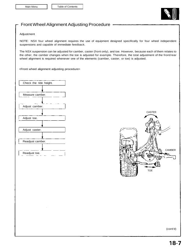
The NSX suspension can be adjusted for camber, caster (front only), and toe. However, because each of them relates to
the other, the camber changes when the toe is adjusted for example. Therefore, the total adjustment of the front/rear
wheel alignment is required whenever one of the elements (camber, caster, or toe) is adjusted.
Check the ride height.
Measure camber.
Adjust camber.
Adjust toe.
Adjust caster.
Readjust camber.
Readjust toe.
(cont’d)
TOE
CAMBER
CASTER
Wheel Alignment
Front Wheel Alignment Adjustment Procedure (cont’d)
NOTE:
NSX four wheel alignment requires the use of equip-
ment designed specifically for four wheel indepen-
dent suspensions and capable of immediate
feedback.
The ride height is very important for setting the align-
ment. For every 10 mm of change in the front ride
height, the camber will change approximately 10
minutes.
The front alignment settings on the NSX are
interactive.
A slight change in toe will dramatically change the
camber.
1. Drive the car on the alignment rack.
2. Check the tire pressure and ride height as described
on page 18 – 6.
3. Center the steering wheel.
Toe
1. Measure the length of the threaded section on
the right and left rack ends.
Standard: 11 mm for shoulder
Difference between right and left: 1 mm max.
2. If the measurement is out of the specification,
loosen the locknut and adjust properly.
LOCKNUT
44 N·m
(4.4 kg-m, 32 Ib-ft)
SHOULDER
Graduation in
contact with
groove wall
DIAL CENTER
GROOVE WALL
Graduation in contact
with groove wall
Loosen the nut
125 N·m
(12.5 kg-m, 90 Ib-ft)
Camber
1. Loosen the locknut on the front lower control
arm adjusting point and adjust the cam posi-
tion so that the right and left graduations on
the adjusting cam are in contact.
2. Mark the arm in the position which aligns with
the dial center of the adjusting cam.
Caster
Loosen the pivot adjuster mounting nuts under
the compliance pivot and adjust the cam posi-
tion so that the right and left graduations on the
adjusting cam are in contact with the groove
walls.
Graduation in contact
with groove wall
GROOVE WALL
Loosen
the nuts
65 N·m
(6.5 kg-m, 47 Ib-ft)
Graduation in
contact with
groove wall
4. Measure and record the readings for the camber
and toe according to the alignment equipment
manufacturer’s instructions.
5. Adjust the camber and toe at the same time on one
side of the car. Repeat for the other side of the car.
NOTE:
One graduation on the camber adjusting cam
equals approximately 10 minutes of camber
change.
One full turn of the tie rod equals approximately
8 mm.
6. Measure the caster according to the alignment
equipment manufacturer’s instructions.
7. Adjust the caster.
NOTE: One graduation on the caster adjusting
cam equals approximately 10 minutes of caster
change.
8. Measure the readings for camber and toe.
9. Readjust the camber and toe to the specifications
shown.
Front Specifications
Toe-out: 3.5 1.0 mm
Camber: -0°20 30
Caster: 8° 00 45