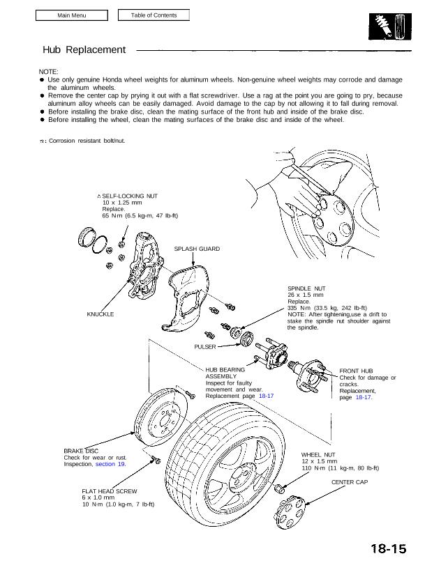
NOTE:
Use only genuine Honda wheel weights for aluminum wheels. Non-genuine wheel weights may corrode and damage
the aluminum wheels.
Remove the center cap by prying it out with a flat screwdriver. Use a rag at the point you are going to pry, because
aluminum alloy wheels can be easily damaged. Avoid damage to the cap by not allowing it to fall during removal.
Before installing the brake disc, clean the mating surface of the front hub and inside of the brake disc.
Before installing the wheel, clean the mating surfaces of the brake disc and inside of the wheel.
Corrosion resistant bolt/nut.
SELF-LOCKING NUT
10 x 1.25 mm
Replace.
65 N.m (6.5 kg-m, 47 Ib-ft)
SPLASH GUARD
KNUCKLE
SPINDLE NUT
26 x 1.5 mm
Replace.
335 N.m (33.5 kg, 242 Ib-ft)
NOTE: After tightening,use a drift to
stake the spindle nut shoulder against
the spindle.
PULSER
HUB BEARING
ASSEMBLY
Inspect for faulty
movement and wear.
Replacement page 18-17
FRONT HUB
Check for damage or
cracks.
Replacement,
page 18-17.
BRAKE DISC
Check for wear or rust.
Inspection, section 19.
FLAT HEAD SCREW
6 x 1.0 mm
10 N.m (1.0 kg-m, 7 Ib-ft)
WHEEL NUT
12 x 1.5 mm
110 N.m (11 kg-m, 80 Ib-ft)
CENTER CAP
Front Suspension
Hub Replacement
1. Loosen the wheel nuts slightly.
2. Raise the front of car and support on safety stands
in proper locations (see section 1).
3. Remove the wheel nuts and wheel.
NOTE: Before installing the wheel, clean the
mating surfaces of the brake disc and inside of the
wheel.
CENTER
CAP
WHEEL NUT
110 N.m
(11 kg-m, 80 lb-ft)
4. Remove the brake hose mounting bolts.
FRONT BRAKE HOSE
BRAKE HOSE MOUNTING BOLTS
Corrosion resistant bolt/nut
5. Remove the wheel sensor from the knuckle and
front lower control arm.
Do not disconnect the wheel sensor.
Be careful when installing the sensors to avoid
twisting wires. 10N.m
(1.0 kg-m, 7 lb-ft)
WHEEL
SENSOR
22 N.m
(2.2 kg-m, 16 Ib-ft)
Corrosion resistant bolt/nut
6. Remove the caliper bracket mounting bolts and
hang the caliper assembly to one side.
CAUTION: To prevent accidental damage to the
caliper assembly or brake hose, use a short piece of
wire to hang the caliper assembly from the
undercarriage.
CALIPER BRACKET MOUNTING BOLTS
110 N.m (11 kg-m, 80 Ib-ft)
10 N.m
(1.0 kg-m. 7 Ib-ft)
Corrosion resistant bolt/nut
22 N.m (2.2 kg-m, 16 Ib-ft)
NOTE:
7. Remove the flat head screws.
Screw two 8 x 1 2 mm bolts into the disc to push it
away from the hub.
NOTE: Turn each bolt two turns at a time to pre-
vent cocking the disc excessively.
FLAT HEAD SCREW
6 x 1.0 mm
10N.m (1.0 kg-m, 7 Ib-ft)
BRAKE DISC 8 x 1 2 mm
BOLTS
8. Remove the hub unit from the knuckle.
SELF-LOCKING NUT
10 x 1.25 mm
Replace.
65 N.m (6.5 kg-m, 47 Ib-ft)
FRONT HUB UNIT
Corrosion resistant bolt/nut
Front Wheel Bearing Replacement:
1. Pry the spindle nut stake away from the spindle,
then remove the spindle nut.
SPINDLE NUT
26 x 1.5 mm
Replace.
Unstake
2. Remove the pulser using a commercially available
bearing puller.
PULSER
(cont’d)
Front Suspension
Hub Replacement (cont’d)
3. Separate the wheel bearing from the hub using the
special tools and a press.
CAUTION: Hold onto the hub to keep it from fall-
ing when pressed clear.
HUB DIS/
ASSEMBLY BASE
07GAF—SD40700
Press WHEEL
BEARING
Replace.
4. Remove the outboard bearing inner race from the
hub using a commercially available bearing puller.
NOTE: Replace the bearing with a new one after
removal.
5. Press a new wheel bearing into the hub using the
special tools shown and a press.
PressHUB ASSEMBLYDRIVER ATTACHMENT
07GAF—SD40200
SUPPORT BASE
07965—SD90100
6. Install the pulser.
NOTE: Be sure the pulser engages with the pin on
the spindle.
PULSER
PIN
INNER RACE
Replace.
NOTE: Wash the bearing and hub thoroughly in
high flash point solvent before reassembly.
7. Tighten the new spindle nut to specified torque,
then stake the spindle nut shoulder against the
spindle.
335 N.m
(33.5 kg-m, 242 Ib-ft)
Stake
After tightening, use a
drift to stake spindle
nut shoulder against
the spindle.