Installation
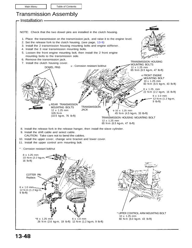
NOTE: Check that the two dowel pins are installed in the clutch housing.
1. Place the transmission on the transmission jack, and raise it to the engine level.
2. Set the release fork to the clutch housing, (see page, 13-9)
3. Install the 2 transmission housing mounting bolts and engine stiffener.
4. Install the 3 rear transmission mounting bolts.
5. Loosen the front engine mounting bolt, then install the 2 front engine
mounting bolts to the transmission side.
6. Remove the transmission jack.
7. Install the clutch housing cover.
DOWEL PINS
REAR TRANSMISSION
MOUNTING BOLTS
12 x 1.25 mm
105 N·m
(10.5 kg-m, 76 Ib-ft)
TRANSMISSION
JACK
8. Install the release fork in the release hanger, then install the slave cylinder.
9. Install the shift cable and select cable.
CAUTION: Take care not to bend the cables.
10. Install the upper cover, change wire bracket and lower cover.
11. Install the upper control arm mounting bolt.
* : Corrosion resistant bolt/nut
8 x 1.25 mm
22 N·m (2.2 kg-m,
16 Ib-ft)
COTTER PIN
Replace.
6 x 1.0 mm
12 N·m (1.2 kg-m,
9 Ib-ft)
*8 x 1.25 mm
26 N·m (2.6 kg-m, 19 Ib-ft)
* UPPER CONTROL ARM MOUNTING BOLT
10 x 1.25 mm
60 N·m (6.0 kg-m. 43 Ib-ft)
Corrosion resistant bolt/nut
TRANSMISSION HOUSING
MOUNTING BOLTS
12 x 1.25 mm
65 N·m (6.5 kg-m, 47 Ib-ft)
FRONT ENGINE
MOUNTING BOLT
10 x 1.25 mm
60 N·m (6.5 kg-m, 43 Ib-ft)
8 x 1.25 mm
22 N·m (2.2 kg-m, 16 Ib-ft)
6 x 1.0 mm
12 N·m (1.2 kg-m,
9 Ib-ft)
10 x 1.25 mm
45 N·m (4.5 kg-m, 33 Ib-ft)
TRANSMISSION HOUSING MOUNTING BOLT
12 x 1.25 mm
65 N·m (6.5 kg-m, 47 Ib-ft)
6 x 1.0 mm
12 N·m (1.2 kg-m, 9 Ib-ft)
12. Install a new set ring on the end of the left driveshaft and intermediate shaft.
13. Install the left driveshaft.
14. Install the lower arm to the side beam.
CAUTION: Align the reference marks on the adjusting bolt, adjusting cam and lower control arm.
15. Install the damper fork bolt.
16. Install the ball joint nut to the toe control arm at the knuckle.
CAUTION: Make sure that the arrow marks on the toe control arm are aligned.
17. Install the ALB sensor wire clamp and parking brake cable holder.
Corrosion resistant bolt/nut
SELF-LOCKING NUT
Replace.
12 x 1.25 mm
95 N·m (9.5 kg-m, 69 Ib-ft)
SELF-LOCKING NUT
Replace.
12 x 1.25 mm
85 N·m (8.5 kg-m, 62 Ib-ft)
6 x 1.0 mm
10 N·m
(1.0 kg-m. 7 Ib-ft)
SELF-LOCKING NUT
14 x 1.5 mm
125 N·m
(12.5 kg-m, 90 Ib-ft)
8 x 1.25 mm
22 N·m (2.2 kg-m, 16 Ib-ft)
12 x 1.25 mm
95 N·m
(9.5 kg-m, 69 Ib-ft)
ADJUSTING
BOLT
ADJUSTING
CAM
SET RING
SELF-LOCKING NUT
Replace.
12 x 1.25 mm
95 N·m (9.5 kg-m, 69 Ib-ft)
18. Install the intermediate shaft and tighten the intermediate shaft mounting bolts to the intermediate shaft support
base.
19. Install the intermediate shaft heat cover.
SET RING 6 x 1.0 mm
10 N·m (1.0 kg-m, 7 Ib-ft)
8 x 1.25 mm
22 N·m
(2.2 kg-m, 16 Ib-ft)
(cont’d)
20. Install the right driveshaft onto the intermediate shaft.
21. Install the castle nut on the lower control arm at the knuckle.
22. Install the damper fork bolt.
23. Install the castle nut on the toe control arm at the knuckle.
CAUTION: Make sure that the arrow marks on the toe control arm are aligned.
24. Install the Anti-lock brake sensor wire clamp and parking brake cable holder.
Transmission Assembly
Installation (cont’d)
Corrosion resistant bolt/nut
6 x 1.0 mm
10 N·m
(1.0 kg-m, 7 Ib-ft)
8 x 1.25 mm
22 N·m (2.2 kg-m, 16 Ib-ft)
SELF-LOCKING NUT
Replace.
12 x 1.25 mm
85 N·m (8.5 kg-m, 62 Ib-ft)
COTTER PIN
Replace.
CASTLE NUT
12 x 1.25 mm
60 N·m
(6.0 kg-m, 43 Ib-ft)
CASTLE NUT
10 x 1.25 mm
44 N·m
(4.4 kg-m, 32 Ib-ft)
COTTER PIN
Replace.
DAMPER FORK BOLT
SELF-LOCKING NUT
Replace.
12 x 1.25 mm
95 N·m (9.5 kg-m, 69 Ib-ft)
25. Install the front exhaust pipe A.
26. Install the rear beam rod.
27. Install the parking brake cable.
SELF-LOCKING NUT
Replace.
10 x 1.25 mm
34 N·m (3.4 kg-m, 25 Ib-ft)
Corrosion resistant bolt/nut
GASKET,
Replace.
10 x 1.25 mm
60 N·m (6.0 kg-m,
43 Ib-ft)
8 x 1.25 mm
22 N·m (2.2 kg-m,
16 Ib-ft)
SELF LOCKING NUT
Replace.
10 x 1.25 mm
55 N·m (5.5 kg-m, 40-lb-ft)
10 x 1.25 mm
60 N·m (6.0 kg-m, 43 Ib-ft)
12 x 1.25 mm
95 N·m (9.5 kg-m, 69 Ib-ft)
8 x 1.25 mm
22 N·m (2.2 kg-m, 16 Ib-ft)
28. Install the transmission mount and 2 transmission
housing mounting bolts.
29. Install the starter motor and connect the starter
motor cables.
30. Install the transmission ground cable and jumper
connector, and connect the back-up light switch,
neutral switch and speed sensor connectors.
31. Install the control box and connect the control box
connectors.
Corrosion resistant bolt/nut
TRANSMISSION HOUSING
MOUNTING BOLTS
12 x 1.25 .mm
65 N·m (6.5 kg-m, 46 Ib-ft)
12 x 1.25 mm
75 N·m (7.5 kg-m, 54 Ib-ft)
12 x 1.25 mm
75 N·m (7.5 kg-m, 54 Ib-ft)
TRANSMISSION MOUNTING
BOLTS
10 x 1.25 mm
60 N·m (6.0 kg-m, 43 Ib-ft)
TRANSMISSION MOUNTING
BOLT
12 x 1.25 mm
95 N·m (9.5 kg-m, 69 Ib-ft)
CONTROL BOX
32. Install the air cleaner case.
33. Install the strut bar.
34. Refill the transmission with oil.
35. Connect the battery positive (+) and negative (-)
cables to the battery.
36. Inspect the rear camber (see section 18).
37. Check the clutch operation.
38. Shift the transmission and check for smooth
operation.