Anti-lock Brake System (ABS) Indicator Light
Temporary Driving Conditions:
1. The ABS indicator light will come on and the ABS
control unit memorizes the diagnostic trouble code
(DTC) under certain conditions.
NOTE: The DTC explained on pages 19-46.
• The tire(s) adhesion is lost due to excessive cor-
nering speed.
DTC: 5, 5-4, 5-8.
• The vehicle loses traction when starting from a
stuck condition on a muddy, snowy, or sandy
road.
DTC: 4-1, 4-2, 4-4, 4-8.
• When the parking brake is applied for more than
30 seconds while the vehicle is being driven.
DTC: 2.
• The vehicle is driven on extremely rough road.
The ABS is OK, if the ABS indicator light goes
off after the engine is restarted.
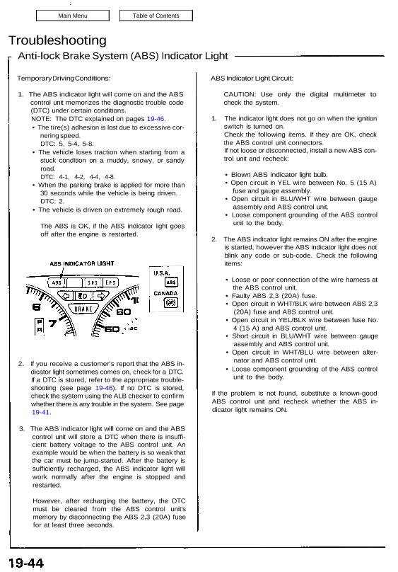
2. If you receive a customer’s report that the ABS in-
dicator light sometimes comes on, check for a DTC.
If a DTC is stored, refer to the appropriate trouble-
shooting (see page 19-46). If no DTC is stored,
check the system using the ALB checker to confirm
whether there is any trouble in the system. See page
19-41.
3. The ABS indicator light will come on and the ABS
control unit will store a DTC when there is insuffi-
cient battery voltage to the ABS control unit. An
example would be when the battery is so weak that
the car must be jump-started. After the battery is
sufficiently recharged, the ABS indicator light will
work normally after the engine is stopped and
restarted.
However, after recharging the battery, the DTC
must be cleared from the ABS control unit’s
memory by disconnecting the ABS 2,3 (20A) fuse
for at least three seconds.
ABS Indicator Light Circuit:
CAUTION: Use only the digital multimeter to
check the system.
1. The indicator light does not go on when the ignition
switch is turned on.
Check the following items. If they are OK, check
the ABS control unit connectors.
If not loose or disconnected, install a new ABS con-
trol unit and recheck:
• Blown ABS indicator light bulb.
• Open circuit in YEL wire between No. 5 (15 A)
fuse and gauge assembly.
• Open circuit in BLU/WHT wire between gauge
assembly and ABS control unit.
• Loose component grounding of the ABS control
unit to the body.
2. The ABS indicator light remains ON after the engine
is started, however the ABS indicator light does not
blink any code or sub-code. Check the following
items:
• Loose or poor connection of the wire harness at
the ABS control unit.
• Faulty ABS 2,3 (20A) fuse.
• Open circuit in WHT/BLK wire between ABS 2,3
(20A) fuse and ABS control unit.
• Open circuit in YEL/BLK wire between fuse No.
4 (15 A) and ABS control unit.
• Short circuit in BLU/WHT wire between gauge
assembly and ABS control unit.
• Open circuit in WHT/BLU wire between alter-
nator and ABS control unit.
• Loose component grounding of the ABS control
unit to the body.
If the problem is not found, substitute a known-good
ABS control unit and recheck whether the ABS in-
dicator light remains ON.
Diagnostic Trouble Code (DTC):
1. Stop the engine.
2. Disconnect the service check connector from the connector cover located under the glove box.
Connect the two terminals of the service check connector with a jumper wire.
3. Turn the ignition switch on, but do not start the engine.
4. Record the blinking frequency of the ABS indicator light.
The blinking frequency indicates the diagnostic trouble code (DTC).
CAUTION: Before starting the engine, disconnect the jumper wire from the service check connector, or else the
Malfunction Indicator Lamp (MIL) will stay on with the engine running.
NOTE:
• The ABS control unit can indicate three DTCs (one, two or three problems).
• If the ABS indicator light does not light, see Troubleshooting of ABS Indicator Light Circuit page 19-44.
• If you miscount the blinking frequency, turn the ignition switch off, then turn on to blink the ABS indicator light
again.
• After the repair is completed, disconnect the ABS 2,3 (20A) fuse for at least three seconds to erase the ABS
control unit’s memory. Then turn the ignition key on again and recheck.
• The memory is erased if the connector is disconnected from the ABS control unit or the ABS control unit is re-
moved from the body.
• After recording the main and sub-code (if applicable), refer to the Symptom-to-System Chart.