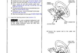
NOTE:
Remove the access panel, then remove the
short connector (RED). Disconnect the connec-
tor between the airbag and cable reel, then con-
nect the short connector (RED) to the airbag
connector.
AIRBAG
CONNECTOR
CABLE REEL
CONNECTOR
ACCESS PANEL
SHORT CONNECTOR
(RED)
Connect the special tool to the cable reel
connector.
CABLE REEL
CONNECTOR
SHORT
CONNECTOR
(RED)
SHS
SERVICE CONNECTOR
07MAZ–SP00200
(cont’d)
SRS components are located in this area. Review the SRS
component locations, precautions, and procedures in the
SRS section (24) before performing repairs or service.
1. To remove the dashboard, first remove the:
Seats (see page 20-39 (’93-’96), 38)
Dashboard lower cover (Driver’s) (see page
20-54(’94-’96) (’91-’93))
Dashboard lower pad (see page 20-54(’94-’96) (’91-’93))
Dashboard brace (see page 20-54(’94-’96)(’91-’93))
Center armrest (see page 20-49(’94-’96)(’91-’93))
Clock, center air vent and console panel (see
pages 20-50(’94-’96) (’91-’93), 51(’94-’96) (’91-’93)
52(’94-’96) (’91-’93))
Climate control unit and stereo elassette/ratio (see
page 20-53(’94-’96)(’91-’93))
Dashboard lower cover (Passenger’s) (see page
20-53(’94-’96) (’91-’93))
Glove box lid and glove box (see page 20-53(’94-’96)(’91-’93))
2. Lower the Steering column (see section 17).
To avoid accidental deployment and
possible injury always install the short connector
on the airbag connector when the SRS wire
harness is disconnected.
Dashboard
Replacement
NOTE: To prevent damage to the steering column,
wrap it with a shop towel.
STEERING COLUMN
8 x 1.25 mm
16 N-m (1.6 kg-m.
12 Ib-ft)
8 x 1.25 mm
23 N-m (2.3 kg-m,
17 Ib-ft)
3. Remove the nuts, then remove the airbag bracket
(passenger’s).
To avoid accidental deployment and
possible injury always install the short connector
on the airbag connector when the SRS wire
harness is disconnected.
NOTE:
• Disconnect the connector between the pas-
senger’s airbag and SRS main wire harness.
Connect the short connector (RED) to the airbag
the connector.
PASSENGER’S AIRBAG SRS MAIN
WIRE HARNESS
SHORT CONNECTOR
(RED)
AIRBAG CONNECTOR
• Connect the special tool to the SRS main wire
harness connector.
PASSENGER’S AIRBAG CONNECTOR/
SHORT CONNECTOR (RED)
SRS MAIN WIRE
HARNESS CONNECTOR SRS SERVICE CONNECTOR
07MAZ-SP00200
PASSENGER’S AIRBAG
AIRBAG BRACKET
© MOUNTING NUT
6 x 1.0 mm 10 N-m
(1.0 kg-m, 7.2 Ib-ft)
SRS MAIN
WIRE HARNESS
© MOUNTING NUT
6 x 1.0 mm 10 N-m
(1.0 kg-m, 7.2 Ib-ft)
• When installing the airbag bracket, tighten the
mounting nuts in the numbered sequence.
4. Remove the instrument panel trim and gauge as-
sembly.
GAUGE ASSEMBLY
INSTRUMENT
PANEL TRIM
CONNECTOR
HOLDER
5. Remove the mounting screws, then remove the side air vents from each side of the dashboard.
6. Remove the dashboard end plate, and fold the console carpet down (see page 20-47(’94-’96) (’91-’93)).
7. Remove the dashboard mounting bolts and screw, then lift and remove the dashboard.
NOTE:
Take care not to scratch the dashboard.
Use protective tape on the bottom of the front pillar trim.
To prevent damage to the shift lever and indicator panel (A/T), wrap them with a shop towel.
CAUTION: When prying with a flat tip screwdriver, wrap it with protective tape or a shop towel to prevent damage.
NOTE: If necessary, remove the defrost panel.
MOUNTING BOLTS
DEFROST
PANEL
MOUNTING BOLTS
DASHBOARD
MOUNTING BOLTS
PROTECTIVE
TAPE
DASHBOARD
GUIDE PIN
SCREW
PASSENGER’S
AIRBAG
DASHBOARD
END PLATE
SIDE AIR VENT
DASHBOARD
MOUNTING SCREWS DASHBOARD
MOUNTING BOLTS
SHOP TOWEL
CONSOLE CARPET
SRS UNIT
DASHBOARD
MOUNTING BOLTS
: CORROSION RESISTANT BOLT
8. Installation is the reverse of the removal procedure.
NOTE:
Make sure the dashboard fits onto the guide pin and defrost panel correctly.
Before tightening the mounting bolts, make sure the wire harnesses are not pinched.
DASHBOARD
RETAINER (4)
DEFROST PANEL