Installation
1. Place the transmission on the transmission jack, and raise to the engine level.
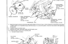
2. Check that the 14 mm and 10 mm dowel pins are installed in the torque converter housing.
3. Install the 3 transmission housing mounting bolts.
4. Install the 3 rear transmission mounting bolts.
5. Loosen the front engine mounting bolt and install the 2 front engine mounting bolts to transmission side, then
tighten the 3 bolts specified torque.
TRANSMISSION HOUSING
MOUNTING BOLT
12 x 1.25 mm
75 N.m (7.5 kg-m, 54 Ib-ft)
DOWEL PIN
14 x 20 mm
FRONT ENGINE
MOUNTING BOLT
10 x 1.25 mm
60 N.m
(6.0 kg-m, 43 Ib-ft)
TRANSMISSION HOUSING
MOUNTING BOLT
12×1.25 mm
75 N.m (7.5 kg-m, 54 Ib-ft)
O-RING
Replace.
DOWEL PIN
10 x 20 mm
TORQUE CONVERTER REAR TRANSMISSION
MOUNTING BOLT
10 x 1.25 mm
60 N·m
(6.0 kg-m, 43 Ib-ft)
TRANSMISSION JACK
7. Attach the torque converter to the drive plate with 8 bolts to 12 N.m (1.2 kg-m, 9 Ib-ft). Rotate the crankshaft as necessary
to tighten bolts to 1/2 of specified torque, then final torque, in a crisscross pattern. Check for free rotation after tightening
the last bolt.
8. Install the torque converter cover.
9. Install the shift cable, shift cable holder and shift cable cover.
10. Install the upper control arm mounting bolt.
6x 1.0 mm
12 N.m
(1.2 kg-m, 9 Ib-ft)6 x 1.0 mm
12 N.m
(1.2 kg-m, 9 Ib-ft)
CONTROL LEVER
UPPER CONTROL ARM MOUNTING BOLT
10 x 1.25 mm
60 N.m (6.0 kg-m, 43 Ib-ft)
6 x 1.0 mm
12 N.m
(1.2 kg-m, 9 Ib-ft)
(cont’d)
6 x 1.0 mm
8 N.m (0.8 kg-m, 6 Ib-ft)
Install in this
direction.
LOCK PIN
CONTROL LEVER
PIN
Corrosion resistant bolt/nut
Corrosion resistant bolt/nut
6. Remove the transmission jack.
Transmission
Installation (cont’d)
11. Install a new set ring on the end of the left driveshaft and intermediate shaft.
12. Install the left driveshaft.
13. Install the lower control arm to the side beam.
CAUTION: Line up the reference marks on the adjusting boh, adjusting cam and lower control arm.
14. Install the damper fork bolt.
15. Install the toe control arm to the side beam.
CAUTION: Make sure that the reference marks on the toe control arm are aligned.
16. Install the wheel sensor wire clamp and parking brake cable holder.
SELF-LOCKING NUT
Replace.
12 x 1.25 mm
95 N.m (9.5 kg-m, 69 Ib-ft)
DAMPER
FORK BOLT
SELF-LOCKING NUT
Replace.
12 x 1.25mm
85 N.m (8.5 kg-m, 62 Ib-ft)
6×1 .0 mm
10 N.m (1.0 kg-m, 7 Ib-ft)
FLANGE BOLT
12 x 1.25 mm
95 N.m (9.5 kg-m, 69 Ib-ft)
TOE CONTROL ARM
SET RING
6 x 1 . 0 mm
Replace.
SELF-LOCKING NUT
ADJUSTING NUT
Replace.
14 x 1.5 mm
125 N.m (12.5 kg-m. 90 Ib-ft)
ADJUSTING CAM
ADJUSTING BOLT
17. Install the intermediate shaft and tighten the intermediate shaft mounting bolts to the intermediate shaft support base.
18. Install the intermediate shaft heat cover.
6×1.0 mm
10 N·m
(1.0 kg-m, 7 Ib-ft)
INTERMEDIATE SHAFT
HEAT COVER
8×1.25 mm
22 N·m
(2.2 kg-m, 16 Ib-ft)
INTERMEDIATE SHAFT
SET RING
Corrosion resistant bolt/nut
10 N.m (1.0 kg-m, 7 Ib-ft)
14 x 1.5 mm
125 N.m
(12.5 kg-m, 90 Ib-ft)
19. Install the right driveshaft on the intermediate shaft.
20. Install the lower control arm to the side beam.
CAUTION: Line up the reference marks on the adjusting bolt, adjusting cam and lower control arm.
21. Install the damper fork bolt.
22. Install the toe control arm to the side beam.
CAUTION: Make sure that the reference marks on the toe control arm are aligned.
23. Install the wheel sensor wire clamp and parking brake cable holder.
Corrosion resistant bolt/nut
SELF-LOCKING NUT
DAMPER FORK
BOLT
SELF-LOCKING NUT
Replace.
12 x 1.25 mm
95 N.m (9.5 kg-m, 69 Ib-ft)
6 x 1.0 mm
FLANGE BOLT
(cont’d)
SELF-LOCKING NUT
Replace.
10 x 1.25 mm
55 N.m (5.5 kg-m, 40 Ib-ft)
10 x 1.25 mm
60 N.m (6.0 kg-m, 43 Ib-ft)
95 N.m (9.5 kg-m, 69 Ib-ft)
12 x 1.25 mm
22 N.m (2.2 kg-m,
16 Ib-ft)
8 x 1.25 mm
22 N.m
(2.2 kg-m, 16 Ib-ft)
8 x 1.25 mm
GASKET
Replace.
SELF-LOCKING NUT
Replace.
10 x 1.25 mm
34 N.m
(3.4 kg-m. 25 Ib-ft)
24. Install the front exhaust pipe A.
25. Install the rear beam rod.
26. Install the parking brake cable.
ADJUSTING CAM
125 N.m (12.5 kg-m, 90 Ib-ft)
ADJUSTING NUT
Replace.
14 x 1.5 mm
TOE CONTROL ARM
95 N.m
(9.5 kg-m, 69 Ib-ft)
Replace.
12 x 1.25 mm
85 N.m
(8.5 kg-m, 62 Ib-ft)
10 N.m
(1.0 kg-m, 7 Ib-ft)
12 x 1.25 mm
Corrosion resistant bolt/nut
ADJUSTING
BOLT
SELF-LOCKING NUT
Replace.
14 x 1.5 mm
12.5 N·m (12.5 kg-m, 90 Ib-ft)
LOWER CONTROL ARM
6 x 1.0 mm
10 N.m (1.0 kg-m, 7 Ib-ft)
Transmission
Installation (cont’d)
27. Install the 3 transmission mounting bolts, and the 2
transmission housing mounting bolts.
28. Install the starter motor and tighten the starter motor
mounting bolts.
29. Install the ATF cooler.
30. Connect the transmission ground cable, starter motor
cable, solenoid valve wire connectors and vehicle
speed sensor (VSS) wire connectors.
31. Install the control box and connect the control box
connectors.
32. Install the air cleaner housing.
33. Install the strut bar.
TORQUE: 39 N.m (3.9 kg-m, 28 Ib-ft)
Corrosion resistant bolt/nut
34. Refill the transmission with ATF.
35. Connect the battery positive (+) and negative ( – ) ca-
ble to the battery.
36. Inspect the rear camber (see section 18).
37. Start the engine. Set the parking brake, and shift the
transmission through all gears three times. Check for
proper shift cable adjustment.
38. Check the ignition timing (see section 23).
39. Let the engine reach normal operating temperature
(the cooling fan comeson) with the transmission in
or position, then turn it off and check the
fluid level.
40. Road test as described on page 14-88.
TRANSMISSION HOUSING
MOUNTING BOLT
12 x 1.25 mm
75 N.m (7.5 kg-m, 54 Ib-ft)
CONTROL BOX
8×1.25 mm
18 N.m (1.8 kg-m,
13 Ib-ft)
TRANSMISSION MOUNTING BOLT
10 x 1.25mm
60 N.m (6.0 kg-m, 43 Ib-ft)
STARTER MOTOR
MOUNTING BOLT
12 x 1.25mm
75 N.m (7.5 kg-m,
54 Ib-ft)