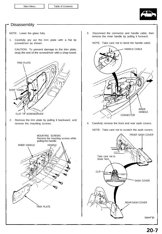
NOTE: Lower the glass fully.
1. Carefully pry out the trim plate with a flat tip
screwdriver as shown.
CAUTION: To prevent damage to the trim plate,
wrap the end of the screwdriver with a shop towel.
TRIM PLATE
SHOP TOWEL
FLAT TIP SCREWDRIVER
2. Remove the trim plate by pulling it backward, and
remove the mounting screws.
MOUNTING SCREWS
Remove the mounting screws while
pulling the handle.
INNER HANDLE HANDLE
TRIM PLATE
3. Disconnect the connector and handle cable, then
remove the inner handle by pulling it forward.
NOTE: Take care not to bend the handle cable.
HANDLE CABLE
INNER
HANDLE
CONNECTOR
4. Carefully remove the front and rear sash covers.
NOTE: Take care not to scratch the sash covers.
FRONT SASH COVER
Take care not to
break here.
CLIP
REAR SASH COVER
SASH COVER
Doors
Disassembly
5. Remove the mounting screws. Lift the door panel
straight up off the sill.
Disconnect the connectors:
• Trunk lid opener
• Power window/Door mirror
• Courtesy light
• Security alarm
CONNECTORS
DOOR PANEL
MOUNTING SCREW
6. Remove the switch panel and air duct from the
door panel as required.
SWITCH PANEL
AIR DUCT
DOOR PANEL
7. Remove the mounting screws and disconnect the
connectors, then remove the power window con-
trol unit and speaker unit.
POWER WINDOW
CONTROL UNIT CONNECTORS
MOUNTING
SCREW
SPEAKER UNIT
CONNECTOR
8. Remove the lower door weatherstrip retaining
clips, then pull off the lower door weatherstrip.
Remove the screw grommets, and carefully remove
the plastic cover.
Clip locations Clip locations
LOWER
WEATHERSTRIP
PLASTIC COVER
SCREW GROMMETS
9. Remove the mounting screws, then remove the
front sash panel from the front sash.
FRONT SASH FRONT SASH PANEL
MOUNTING
SCREW
10. Remove the outer molding (see page 20-12
(’93-’96),11(’91-’92)
11. Remove the mounting bolts and locknut, then
remove the front sash.
NOTE:
Hold the adjusting bolt with a hex wrench when
removing the locknut.
Scribe a line around the locknut to show the
original adjustment.
LOCKNUT
FRONT SASH
ADJUSTING BOLT
MOUNTING BOLT
6 x 1.0 mm
8 N·m (0.8 kg-m,
5.8 lb-ft)
MOUNTING BOLT
*6 x 1.0 mm
8 N·m (0.8 kg-m,
5.8 Ib-ft)
LOCKNUT
*8 x 1.25 mm
22 N·m(2.2kg-m,
16 Ib-ft)
LOCKNUT
: CORROSION RESISTANT BOLT/NUT
12. Remove the mounting bolt, locknut and adjusting
bolt. Remove the rear sash, then disconnect the
handle rod.
NOTE:
Before removing the adjusting bolt, measure and
record the clearance between the rear sash
and door.
Scribe a line around the locknut to show the
original adjustment.
Take care not to bend the handle rod.
HANDLE ROD
REAR SASH
REAR
SASH
DOOR
LOCKNUT
ADJUSTING
BOLT
MOUNTING BOLT
*6 x 1.0 mm
8 N·m 40.8 kg-m,
5.8 Ib-ft)LOCKNUT
*8 x 1.25 mm
22 N·m (2.2 kg-m,
16 Ib-ft)
*: CORROSION RESISTANT 80LT/NUT
13. To replace the outer handle, remove the mounting
screws from the rear sash.
NOTE: Apply grease to the moving surfaces.
OUTER HANDLE
MOUNTING
SCREW
CAP
REAR SASH
(cont’d)
Doors
Disassembly
14. Remove the locknuts, then remove the rear glass
guide.
NOTE:
• Hold the adjusting bolt with a hex wrench when
removing the locknuts.
• Scribe a line around the locknuts to show the
original adjustment.
LOCKNUT
LOCKNUTS
8 x 1.25 mm
22 N-m (2.2 kg-m,
16 Ib-ft)
CORROSION RESISTANT BOLT/NUT
15. Before removing the latch assembly and lock
cylinder, raise the glass fully by connecting a 12 V
battery to the power window motor (see
section 23).
16. Remove the retainer by sliding it forward. Pry the
cylinder rod out its joint using a flat tip screwdriver,
then carefully remove the lock cylinder.
NOTE: Take care not to bend the cylinder rod.
LOCK CYLINDER
CYLINDER ROD
17. Disconnect the lock rod and remove the lock crank.
Remove the handle cable and clips.
Remove the mounting screws, then remove the
latch assembly through the hole in the door.
NOTE: Take care not to bend the lock rod and han-
dle cable.
LATCH ASSEMBLY
HANDLE CABLE
MOUNTING SCREW
6 x 1.0 mm
5 N-m (0.5 kg-m,
3.6 Ib-ft)
CLIPS
LOCK CRANK
LOCK ROD
18. Lower the glass and remove the mounting nuts,
then remove the stopper plates.
NOTE:
• Lower the glass by connecting a 12 V battery to
the power window motor (see section 23).
• Scribe a line around the mounting nuts to show
the original adjustment.
STOPPER PLATES
MOUNTING NUT
8 x 1.25 mm
22 N-m (2.2 kg-m,
16 Ib-ft)
MOUNTING
NUT
RETAINER
GLASS
CYLINDER ROD
ADJUSTING BOLT
REAR GLASS GUIDE
19. Carefully lower the glass until you can see its
mounting bolts, then remove them. Pull the glass
out through the window slot.
NOTE:
• Lower the glass by connecting a 12 V battery to
the power window motor (see section 23).
• Scribe a line around the mounting bolts to show
the original adjustment.
GLASS
GLASS GUIDE
MOUNTING BOLTS
6 x 1.0 mm
8 N-m (0.8 kg-m,
5.8 Ib-ft)
CORROSION RESISTANT
BOLT
20. Remove the locknuts, then remove the front glass
guide.
NOTE:
• Hold the adjusting bolt with a hex wrench when
removing the locknuts.
• Scribe a line around the locknuts to show the
original adjustment.
FRONT GLASS GUIDE LOCKNUT
LOCKNUTS
8 x 1.25 mm
22 N-m (2.2 kg-m,
16 Ib-ft)
21. Remove the mounting bolts and loosen the motor
mounting bolts, then take out the regulator
assembly through the window slot.
NOTE:
• Scribe a line around the mounting bolts to show
the original adjustment.
• Take care not to bend the cables.
CABLES
MOTOR MOUNTING
BOLTS
6 x 1.0 mm 8 N-m
(0.8 kg-m, 5.8 Ib-ft)
Loosen.
MOUNTING BOLTS
6 x 1.0 mm
8 N-m (0.8 kg-m,
5.8 Ib-ft)
MOUNTING
BOLT
CORROSION RESISTANT BOLT
22. Remove the mounting bolts, then remove the inside
stabilizers from the door.
NOTE: Scribe a line around the mounting bolts to
show the original adjustment.
INSIDE STABILIZERS
MOUNTING BOLT
8 x 1.25 mm
22 N-m (2.2 kg-m, 16 Ib-ft)
MOUNTING
BOLT
CORROSION RESISTANT BOLT
GLASS
GLASS