Removal
Engine removal is not required in this procedure.
CAUTION: To avoid damaging the cylinder heads, wait
until the engine coolant temperature drops below
100°F (38°C) before loosening the retaining bolts.
NOTE:
Inspect the timing belt before removing the cylinder
heads.
Turn the crankshaft so that the No. 1 piston is at top
dead center (TDC (page 6-25, 26).
Mark all emission hoses before disconnecting them.
1. Disconnect the negative terminal from the battery.
2. Remove the expansion tank cap.
Use care when removing the expan-
sion tank cap to avoid scalding by engine coolant or
steam.
3. Raise the car.
4. Remove the right rear wheel/tire.
5. Remove the engine under guard, then remove the
front exhaust pipe.
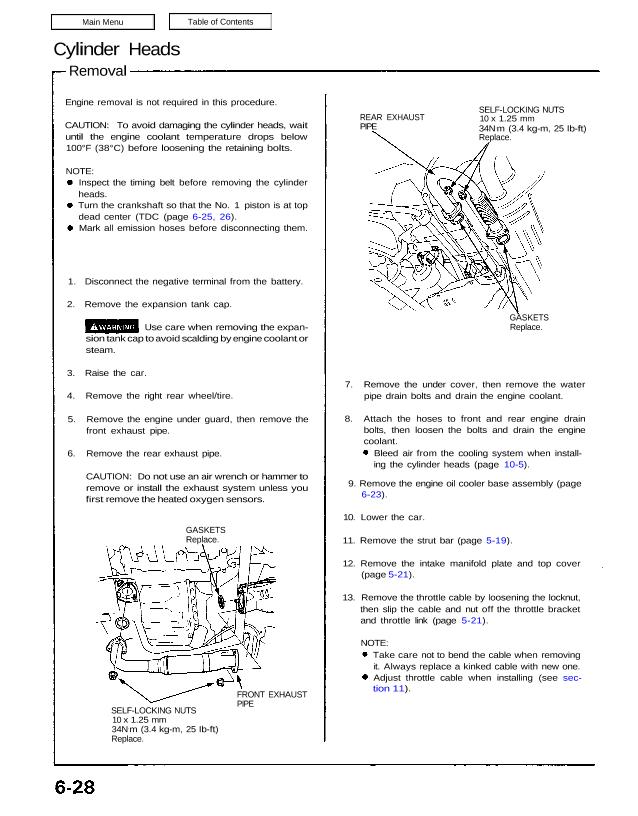
6. Remove the rear exhaust pipe.
CAUTION: Do not use an air wrench or hammer to
remove or install the exhaust system unless you
first remove the heated oxygen sensors.
GASKETS
Replace.
FRONT EXHAUST
PIPE
SELF-LOCKING NUTS
10 x 1.25 mm
34N.m (3.4 kg-m, 25 Ib-ft)
Replace.
REAR EXHAUST
PIPE
SELF-LOCKING NUTS
10 x 1.25 mm
34N.m (3.4 kg-m, 25 Ib-ft)
Replace.
GASKETS
Replace.
7. Remove the under cover, then remove the water
pipe drain bolts and drain the engine coolant.
8. Attach the hoses to front and rear engine drain
bolts, then loosen the bolts and drain the engine
coolant.
Bleed air from the cooling system when install-
ing the cylinder heads (page 10-5).
9. Remove the engine oil cooler base assembly (page
6-23).
10. Lower the car.
11. Remove the strut bar (page 5-19).
12. Remove the intake manifold plate and top cover
(page 5-21).
13. Remove the throttle cable by loosening the locknut,
then slip the cable and nut off the throttle bracket
and throttle link (page 5-21).
NOTE:
Take care not to bend the cable when removing
it. Always replace a kinked cable with new one.
Adjust throttle cable when installing (see sec-
tion 11).
14. Relieve fuel pressure (see section 11).
Do not smoke while working on fuel
system; keep open flame or spark away from work
area. Drain fuel only into an approved container.
1 5. Disconnect the fuel feed pipe and the return hose
(page 5-21).
16. Remove the ignition coil covers, the wire harness
covers, the ignition coils and the connectors (page
6-23).
17. Remove the water hoses, then remove the expan-
sion tank (page 5-21).
18. Remove the breather hose, and the air cleaner
housing (page 5-22).
19. Remove the brake booster hose, the evaporative
emission (EVAP) control canister hose and other
hoses from the intake manifold and throttle body
(page 5-22).
20. Remove the emission control box (page 5-23).
Do not disconnect emission hose.
Disconnect the three connectors before
removing.
21. Remove the connector, the terminal and the
alternator.
22. Disconnect the following engine wire harness con-
nectors, then remove the harness clamps from the
cylinder head and the intake manifold.
Front cylinder head:
Crankshaft position (CKP)/cylinder position
(CYP) sensor connector
Air conditioning (A/C) compressor magnetic
clutch connector
Heated oxygen sensor (H02S) connector
Ground cable terminals
Three injector connectors (cylinders No. 4, 5
and 6)
Intake air temperature (IAT) sensor connector
Ignition control module (ICM) connector
Condenser connector
Engine oil pressure gauge sending unit
connector
VTEC solenoid valve connector
VTEC pressure switch connector
Engine coolant temperature (ECT) sensor
connector
ECT sending unit connector
Accelerator pedal opening sensor connector
(throttle body)
Radiator fan control sensor connector
Rear cylinder head:
Engine oil pressure switch connector (oil cooler
base)
Heated oxygen sensor connector
Three injector connectors (cylinders No. 1, 2
and 3)
Idle air control (IAC) valve connector
Knock sensor connector
Throttle actuator motor connector
Throttle position sensor connector
VTEC solenoid valve connector
VTEC pressure switch connector
ICM connector
Ground terminal
ICM CONNECTORS
THROTTLE ACTUATOR
MOTOR CONNECTOR
THROTTLE POSITION
SENSOR CONNECTOR
ACCELERATOR PEDAL OPENING
SENSOR CONNECTOR
Cylinder Heads
Removal (cont’d)
23. Remove the exhaust gas recirculation (EGR) pipe
and the intake manifold assembly.
NOTE: Fill the cylinder head intake ports with clean
shop towels to prevent foreign materials from get-
ting into the cylinders.
8 x 1.25 mm
22N.m (2.2 kg-m,
16 Ib-ft)
EGR PIPE
MOUNTING BOLT
6 x 1.0 mm
12N.m (1.2 kg-m,
9 Ib-ft)
EGR PIPE
GASKET
Replace.
INTAKE MANIFOLD
GASKET
Replace.
GROUND CABLE
6 x 1.0 mm
12N.m (1.2 kg-m,
9 Ib-ft)
POSITIVE CRANKCASE VENTILATION
(PCV) HOSE
Remove.
IAT SENSOR
CONNECTOR
INJECTOR CONNECTOR
(No. 4 CYLINDER)
GROUND
CABLE
INJECTOR
CONNECTOR
(No.1 CYLINDER)
(cont’d)
29. Remove the water passage.
O-RINGS
Replace.
CONNECTING PIPE
WATER PASSAGE
8 x 1.25 mm
22N.m (2.2 kg-m. 16 Ib-ft)
30. Remove the cylinder head covers.
31. Turn the crankshaft so that the No. 1 piston is at top
dead center (page 6-25, 26).
32. Install a brace under the engine, then tilt the engine
approximately 5° using a jack (page 6-24).
33. Remove the alternator bracket.
8 x 1.25 mm
22N.m (2.2 kg-m, 16 Ib-ft)
10 x 1.25 mm
45N.m (4.5 kg-m.
33 Ib-ft)
ALTERNATOR
BRACKET
24. Remove the bolt from the side engine mount, then
push the side mounting bracket into the housing of
the body (page 5-27).
25. Remove the transmission mount.
26. Remove the alternator bracket stiffener (page 6-24).
27. Disconnect the knock sensor connectors, then re-
move the wire holder.
6 x 1.0 mm
12N.m (1.2 kg-m. 9 Ib-ft)
KNOCK SENSOR
WIRE HOLDER
28. Remove the heater hose and the water hoses.
WATER HOSES
HEATER HOSE
Cylinder Head
Removal (cont’d)
34. Remove the A/C compressor adjusting pulley and
belt.
33. Remove the dipstick pipe mounting bolt, then re-
move the front and rear timing belt middle covers.
35. Remove the crankshaft pulley, then remove the tim-
ing belt lower cover.
36. Loosen the timing belt adjusting bolt 180° and
release the belt tension.
NOTE: Push the tensioner to release tension from
the belt, then retighten the adjusting bolt.
ADJUSTING BOLT
Do not remove.
Loosen it 180°.
37. Remove the timing belt from the pulleys.
CAUTION: Do not crimp or bend the timing belt
more than 90° or less than 25 mm (1 in) in diameter.
FRONT TIMING BELT
COVER PLATE
RUBBER SEALS
39. Remove the front and rear timing belt cover plates.
REAR TIMING BELT
COVER PLATE
RETAINING
BOLTS
CAMSHAFT PULLEYS
38. Remove the camshaft pulleys.
A/C compressor adjusting pulley and A/C com-
pressor belt
Timing belt lower cover
Crankshaft pulley
NOTE: Removal of the following items is not necessary
if only the rear cylinder head is going to be removed.
40. Loosen the valve locknuts and the adjusting
screws.
41. Remove the camshaft holder pipes, the camshaft
holders and the camshafts.
CAMSHAFT HOLDER
PIPES
FRONT INTAKE
CAMSHAFT
RUBBER SEAL
FRONT EXHAUST
CAMSHAFT
OIL SEALS
Replace.
42. Screw a 5 mm bolt into each rocker shaft orifice,
then pull out the rocker shaft orifices.
ROCKER SHAFT
ORIFICE
O-RING
Replace.
5 mm BOLT
O-RING
Replace.
(cont’d)
12 mm BOLT
12 mm BOLT
ROCKER ARM
ASSEMBLY
RUBBER BAND
SEALING VTEC VALVE
BOLT
45. Bundle the rocker arms with rubber bands to keep
them together as sets.
46. Screw a 12 x 1.25 mm bolt into each rocker
shaft. Remove the rocker arms while slowly pull-
ing the rocker shafts out of the cylinder heads
toward the transmission.
FILTER
Replace.
WASHER
Replace.
43. Remove the VTEC valve assemblies.
44. Remove the sealing bolts.
WASHER
Replace.
SEALING BOLT
Cylinder Heads
Removal (cont’d)
47. Disconnect the connectors and remove the engine
wire harness.
48. Remove the cylinder head bolts, then remove the
cylinder heads.
CAUTION: To prevent war page, unscrew the bolts
in sequence 1 /3 turn at a time; repeat the sequence
until all bolts are loosened.
CYLINDER HEAD BOLTS LOOSENING SEQUENCE
49. Remove the front and rear exhaust manifold covers,
then remove the front and rear exhaust manifolds.
CAUTION: Do not use an air wrench or hammer to
remove the exhaust system unless you first remove
the heated oxygen sensor.
NOTE: Separate the cylinder head from the block with
a flat blade screwdriver as shown.