Adjustment
NOTE: NSX/NSX-T four wheel alignment requires the use of equipment designed specifically for four wheel independent
suspensions and capable of immediate feedback.
The NSX/NSX-T suspension can be adjusted for camber, caster (front only), and toe. However, because each of them
relates to the other, the camber changes when the toe is adjusted for example. Therefore, the total adjustment of the
front/rear wheel alignment is required whenever one of the elements (camber, caster, or toe) is adjusted.
Front wheel alignment adjusting procedure
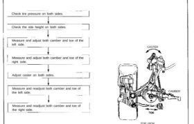
Check tire pressure on both sides.
Check the ride height on both sides.
Measure and adjust both camber and toe of the
left side.
Measure and adjust both camber and toe of the
right side.
Adjust caster on both sides.
Measure and readjust both camber and toe of
the left side.
Measure and readjust both camber and toe of
the right side.
CASTER
TOP VIEW
CAMBER
Wheel Alignment
Front Wheel Alignment Adjustment Procedure
NOTE:
• NSX/NSX-T four wheel alignment requires the use of
equipment designed specifically for four wheel in-
dependent suspensions and capable of immediate
feedback.
• The ride height is very important for setting the align-
ment. For every 10 mm (0.4 in) of change in the
front ride height, the camber will change approx-
imately 10 minutes.
• The front alignment settings on the NSX are
interactive.
• A slight change in toe will dramatically change the
camber.
• Always inspect and adjust the front wheel alignment
with the steering wheel in the straight ahead
position.
1. Drive the car on the alignment rack.
2. Check the tire pressure and ride height (see page
18-6).
3. Center the steering wheel in the straight ahead
position, and lock it in place with the steering lock.
4. Set the alignment equipment following the
manufacturer’s instructions.
5. Measure and adjust the camber and toe on the left
side, then measure and adjust the right side.
Toe:
— Loosen the locknut, and turn the right and left
tie-rods to adjust the front toe.
LOCKNUT
44 N-m
(4.4 kg-m, 32 Ib-ft) TIE-ROD
Camber:
— Loosen the self-locking nut on the front lower
control arm adjusting point, and adjust the
camber by turning the adjusting cam.
SELF-LOCKING NUT
Replace.
125 N-m
(12.5 kg-m, 90 Ib-ft)
Corrosion resistant bolt/nut
6. Measure the caster on the both sides, and adjust the
caster to specifications.
Caster:
• Loosen the pivot adjuster mounting nuts (self-
locking nuts) under the compliance pivot, and
adjust the caster by turning the adjusting cam.
SELF-LOCKING
NUT
Replace.
85 N-m
(8.5 kg-m, 61 Ib-ft)
ADJUSTING CAM
Corrosion resistant bolt/nut
7. Remeasure and, if necessary, adjust the camber and
toe on the left side first, then the right side.
Front Specifications
Toe-out: 3.5 ± 1.0 mm (0.14 ± 0.04 in)
Camber: -0° 20′ ± 30′
Caster: 8° 00′ ± 45′