Piston Rings
Ring-to-Groove Clearances
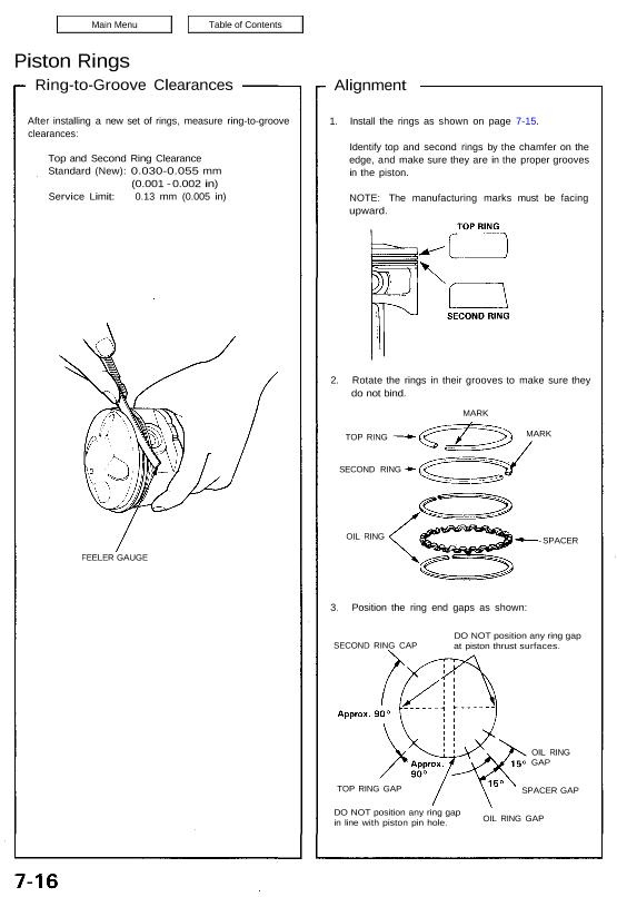
After installing a new set of rings, measure ring-to-groove
clearances:
Top and Second Ring Clearance
Standard (New): 0.030-0.055 mm
(0.001 – 0.002 in)
Service Limit: 0.13 mm (0.005 in)
FEELER GAUGE
Alignment
1. Install the rings as shown on page 7-15.
Identify top and second rings by the chamfer on the
edge, and make sure they are in the proper grooves
in the piston.
NOTE: The manufacturing marks must be facing
upward.
2. Rotate the rings in their grooves to make sure they
do not bind.
MARK
TOP RING
SECOND RING
OIL RING
MARK
– SPACER
3. Position the ring end gaps as shown:
SECOND RING CAP
DO NOT position any ring gap
at piston thrust surfaces.
TOP RING GAP
DO NOT position any ring gap
in line with piston pin hole. OIL RING GAP
SPACER GAP
OIL RING
GAP
