Category: Automatic Transmission
Categories
nsxd14122a.pdf
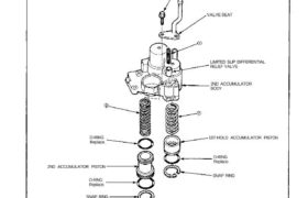
SPRING SPECIFICATIONS SNAP RING SNAP RING Unit of length: mm (in) O-RING Replace. 1ST-HOLD ACCUMULATOR PISTON O-RING Replace. 2ND ACCUMULATOR PISTON O-RING Replace. 2ND ACCUMULATOR BODY LIMITED SLIP DIFFERENTIAL RELIEF VALVE VALVE SEAT 6 x 1.0 mm 12N.m (1.2 kg-m, 9 Ib-ft) Clean all parts thoroughly in solvent or carburetor cleaner, and dry with compressed […]
Categories
nsxd14141a.pdf
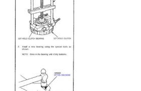
1st-hold Clutch Bearing Replacement 1. Remove the 1st-hold clutch bearing using a bearing puller. BEARING PULLER 1ST-HOLD CLUTCH BEARING 1ST-HOLD CLUTCH 2. Install a new bearing using the special tools as shown. NOTE: Drive in the bearing until it fully bottoms. DRIVER 07749–0010000 ATTACHMENT, 72 x 75 mm 07746–0010600 Attachments nsxd14141a (125 kB)
Categories
nsxd14102a.pdf
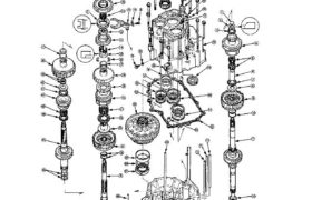
Illustrated Index Transmission Housing Table of Contents Main Menu Illustrated Index Transmission Housing 14-102 SNAP RING WASHER THRUST NEEDLE BEARING MAINSHAFT 4TH GEAR NEEDLE BEARINGS MAINSHAFT 4TH GEAR COLLAR THRUST NEEDLE BEARING THRUST WASHER 4TH CLUTCH ASSEMBLY O-RING Replace. MAINSHAFT SEALING RING 37 mm NEEDLE BEARING SET RING REVERSE SHIFT FORK LOCK WASHER Replace. COUNTERSHAFT […]
Categories
nsxd14083a.pdf
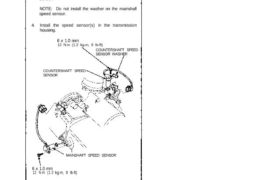
Mainshaft/Countershaft Speed Sensors Replacement 1. Remove the 6 mm bolt from the transmission hous- ing and remove the mainshaft and countershaft speed sensors. 2. Replace the O-ring with a new one before reassembling the mainshaft and countershaft speed sensors. 3. Install the washer on the countershaft speed sensor. NOTE: Do not install the washer on […]
Categories
nsxd14002a.pdf
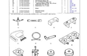
Ref. No. Tool Number Description Must be used with commercially available 3/8 in. x16 threads/in. slide hammer. Special Tools Page Reference 14-107 14-135, 138 14-135, 138 14-135, 138 14-51, 88 14-92 14-92 14-92 14-92 14-143 14-141, 143 14-141, 142, 143 14-141, 142, 143 14-106, 149 14-142 07HAC-PK4010A 07GAE-PG40200 07HAE-PL50100 07LAE-PX40100 07LAJ-PT3010A 07MAJ-PY4011A 07MAJ-PY40120 07406-0020400 07406-0070300 […]
Categories
nsxd14039a.pdf
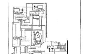
Lock-up System In position and position in 2nd, 3rd and 4th, pressurized fluid is drained from the back of the torque converter through an oil passage, causing the lock-up piston to be held against the torque converter cover. As this takes place, the mainshaft rotates at the same speed as the engine crankshaft. Together with […]
Categories
nsxd14158a.pdf
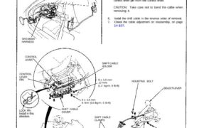
BRACKET BEAM COTTER PIN Replace. SELECT LEVER PIN SELECT LEVER MOUNTING BOLT SHIFT CABLE HOLDER 6 x 1.0 mm 12 N.m (1.2 kg-m, 9 Ib-ft) 6 x 1.0 mm 8 N.m (0.8 kg-m, 6 Ib-ft) SHIFT CABLE CLAMPS SHIFT CABLE COVERLOCK PINInstall in this direction. CONTROL LEVER LEVER CONTROL SRS MAIN HARNESS Make sure lifts […]
Categories
nsxd14125a.pdf
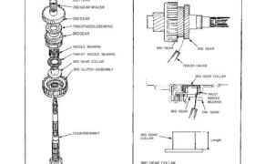
Inspection/Installation NOTE: Lubricate all parts with ATF during assembly. 1. Assemble the parts below on the countershaft. NOTE: Do not install the O-rings during inspection. COTTERS 2ND GEAR SPACER 2ND GEAR THRUST NEEDLE BEARING 3RD GEAR NEEDLE BEARING THRUST NEEDLE BEARING 3RD GEAR COLLAR 3RD CLUTCH ASSEMBLY COUNTERSHAFT 2. Hold the 2nd gear against the […]
Categories
nsxd14123a.pdf
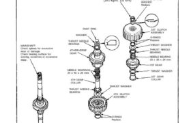
SEALING RINGS NEEDLE BEARING SET RING O-RINGS Replace. 4TH CLUTCH ASSEMBLY THRUST WASHER THRUST NEEDLE BEARING 1ST GEAR COLLAR THRUST WASHER 1ST GEAR NEEDLE BEARING 33 x 38 x 24 mm THRUST NEEDLE BEARING THRUST WASHER O-RINGS Replace. 1ST CLUTCH ASSEMBLY CONICAL SPRING WASHER Replace. LOCKNUT Replace. 140 N.m (14.0 kg-m, 101 Ib-ft) SNAP RING […]
Categories
nsxd14108a.pdf
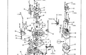
Replace. 7 Bolts 5 Bolts 2 Bolts 2 Bolts Replace. 2 Bolts 5 Bolts 4 Bolts 7 Bolts Valve Body Removal NOTE: 1. Remove the valve body in the following numbered sequence. CAUTION: Do not use a magnet to remove the check balls; it may magnetize the balls. Clean all parts thoroughly in solvent or […]