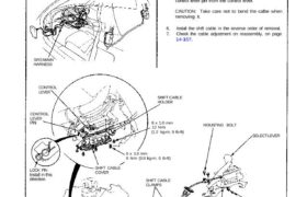
BRACKET BEAM
COTTER PIN
Replace.
SELECT
LEVER PIN
SELECT LEVER
MOUNTING BOLT
SHIFT CABLE
HOLDER
6 x 1.0 mm
12 N.m
(1.2 kg-m, 9 Ib-ft)
6 x 1.0 mm
8 N.m (0.8 kg-m, 6 Ib-ft)
SHIFT CABLE
CLAMPS
SHIFT CABLE
COVERLOCK PINInstall in this
direction.
CONTROL
LEVER
LEVER
CONTROL
SRS MAIN
HARNESS
Make sure lifts are placed properly.
1. Remove the center console panel (see section 20).
2. Remove the shift cable by removing the cotter pin and
selector lever pin from the selector lever, and mount-
ing bolts from the bracket beam.
3. Remove the shift cable clamps.
4. Remove the shift cable holder and shift cable cover.
5. Remove the shift cable by removing the lock pin and
control lever pin from the control lever.
CAUTION: Take care not to bend the calbe when
removing it.
6. Install the shift cable in the reverse order of removal.
7. Check the cable adjustment on reassembly, on page
14-157.
Shift Cable
Removal/Installation
All SRS wiring harnesses are covered with yellow
outer insulation.
Before disconnecting any part of the SRS wire
harness, install the short connectors (see page
23-328).
Replace the entire affected SRS harness assembly if
it has an open circuit or damaged wiring.
CAUTION:
PIN