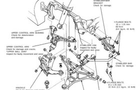
Knuckle/Control Arms
Illustrated Index
Overall Suspension
NOTE:
• Wipe off the grease before tightening the nut at the ball joint.
• Torque specifications, see page 18-30.
• Align the white line on the stabilizer bar with the bushing end, and install the stabilizer bar.
Corrosion resistant bolt/nut
REAR DAMPER
STABILIZER BAR
BRACKET
Check for damage.
UPPER CONTROL ARM BUSHING
Check for deterioration
and damage.
UPPER CONTROL ARM
Check for damage and cracks.
*UPPER BALL JOINT
Inspect for faulty movement and wear.
KNUCKLE
Check for damage and cracks.
LOWER CONTROL BALL JOINT
Inspect for faulty movement
and wear.
FLANGE BOLTS
10 x 1.25 mm
60 N-m
(6.0 kg-m, 43 Ib-ft)
STABILIZER BAR
Check for damage.
FLANGE BOLTS
8 x 1.25 mm
22 N-m (2.2 kg-m, 16 Ib-ft)
TOE CONTROL ARM BUSHING
Check for deterioration and damage.
LOWER CONTROL ARM
Check for damage and cracks.
TOE CONTROL ARM
Check for damage and cracks.
BALL JOINT
Inspect for faulty movement and wear.
NOTE: Replace the joint boot if damaged. The parts marked with an asterisk ( * ) have a retainer attaching the ball
joints. Replace the retainer whenever the boot is replaced.
CAUTION:
• Do not remove the arms and knuckle by striking them with a hammer, and take care not to drop them.
• Make sure that the reference marks on the toe control arm are aligned.
STABILIZER LINK
Inspect for faulty
movement and wear.