In position and position in 2nd, 3rd and 4th, pressurized fluid is drained from the back of the torque converter
through an oil passage, causing the lock-up piston to be held against the torque converter cover. As this takes place, the
mainshaft rotates at the same speed as the engine crankshaft. Together with hydraulic control, the TCM optimizes the
timing of the lock-up system. Under certain conditions, the lock-up operation is applied during deceleration, in 3rd and
4th speed.
The lock-up shift valve controls the range of lock-up according to lock-up control solenoid valves A and B, and throttle
valve B. When lock-up control solenoid valves A and B activate, modulator pressure changes. Lock-up control solenoid
valves A and B are mounted on the torque converter housing, and are controlled by the TCM.
(cont’d)
Description
Lock-up System (cont’d)
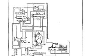
No Lock-up
Pressurized fluid regulated by the modulator works on both ends of the lock-up shift valve and on the left side of the lock-
up control valve. Under this condition, the pressure on both ends of the lock-up shift valve are equal, and the shift valve is
moved to the right side by the tension of the valve spring alone. The fluid from the oil pump will flow through the left side
of the lock-up clutch to the torque converter; i.e., the lock up clutch is in OFF condition.
NOTE: When used, “left” or “right” indicates direction on the flowchart.
THROTTLE B PRESSURE
Partial Lock-up
Lock-up Control Solenoid Valve A: ON Lock-up Control Solenoid Valve B: OFF
The TCM switches the solenoid valve A to ON to release the modulator pressure in the left cavity of the lock-up shift
valve. The modulator pressure in the right cavity of the lock-up shift valve overcomes the spring force, thus the lock-up
shift valve is moved to the left side.
The torque converter pressure is spearated into two passages:
Torque Converter Inner Pressure: entered into right side—to engage lock-up clutch
Torque Converter Back Pressure: entered into left side—to disengage lock-up clutch
The back pressure (F2) is regulated by the lock-up control valve whereas the position of the lock-up timing valve B is
determined by the throttle B pressure, tension of the valve spring and pressure regulated by the modulator. Also the
position of the lock-up control valve is determind by the throttle valve B pressure, back pressure of the lock-up control
valve and torque converter pressure regulated by the check valve. In low speed range, the throttle B pressure working
on the right side of the lock-up control valve is low, causing the valve to be moved to the right side. With the lock-up
control solenoid valve B kept OFF, the modulator pressure is maintained in the left end of the lock-up control valve; in
other words, the lock-up control valve is moved slightly to the left side. This slight movement of the lock-up control
valve causes the back pressure to be lowered slightly, resulting in partial lock-up.
NOTE: When used, “left” or “right” indicates direction on the flowchart.
THROTTLE B PRESSURE
MODULATOR PRESSURE
(cont’d)
Description
Lock-up System (cont’d)
Half Lock-up
Lock-up Control Solenoid Valve A: ON Lock-up Control Solenoid Valve B: ON
The modulator pressure is released by the solenoid valve B, causing the modulator pressure in the left cavity of the lock-
up control valve to lower.
Also the modulator pressure in the left cavity of the lock-up timing valve B is low. However the throttle B pressure is
still low at this time, consequently the lock-up timing valve B is kept on the right side by the spring force.
With the lock-up control solenoid valve B turned ON, the lock-up control valve is moved somewhat to the right side,
causing the back pressure (F2) to lower. This allows a greater amount of the fluid (F1) to work on the lock-up clutch
so as to engage the clutch. The back pressure (F2) which still exists prevents the clutch from engaging fully.
NOTE: When used, “left” or “right” indicates direction on the flowchart.
MODULATOR PRESSURE
THROTTLE B PRESSURE
Full Lock-up
Lock-up Control Solenoid Valve A: ON Lock-up Control Solenoid Valve B: ON
When the vehicle speed further increases, the throttle B pressure is increased in accordance with the throttle opening.
The lock-up timing valve B overcomes the spring force and moves to the left side. Also this valve closes the oil port
leading to the torque converter check valve.
Under this condition, the throttle B pressure working on the right end of the lock-up control valve becomes greater than
that on the left end (modulator pressure in the left end has already been released by the solenoid valve B); i. e., the lock-
up control valve is moved to the left side. As this happens, the torque converter back pressure is released fully, causing
the lock-up clutch to be engaged fully.
NOTE: When used, “left” or “right” indicates direction on the flowchart.
MODULATOR PRESSURE
(cont’d)
THROTTLE B PRESSURE
Description
Lock-up System (cont’d)
Deceleration Lock-up
Lock-up Control Solenoid Valve A: ON Lock-up Control Solenoid Valve B: Duty Operation (ON OFF)
The TCM switches the solenoid valve B to ON and OFF alternately at high speeds under certain conditions.
The slight lock-up and half lock-up regions are maintained so as to lock the torque converter properly.
NOTE: When used, “left” or “right” indicates direction on the flow chart.
MODULATOR PRESSURE
THROTTLE B PRESSURE