Category: Fuel & Emissions
Categories
nsxe11080a.pdf
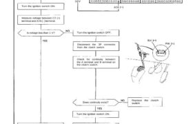
Idle Control System Troubleshooting Flowchart Clutch Switch Signal This signals the PGM-FI ECU when the clutch is engaged. Inspection of clutch switch signal. Connect the ECU test harness between the ECU and connector (page 11-21). Less than 1 V? 10V A26 C7 Turn the ignition switch ON. Measure voltage between C7 (+) terminal and A26 […]
Categories
nsxd11136a.pdf
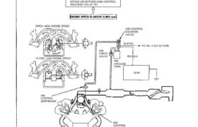
Intake Air System Description Satisfactory power performance is achieved by closing and opening the intake air bypass (IAB) control valves. High tor- que at low engine speed is achieved when the valves are closed, whereas high power at high engine speed is achieved when the valves are opened. Intake Air Bypass (IAB) Control System OPEN: […]
Categories
nsxd11152a.pdf
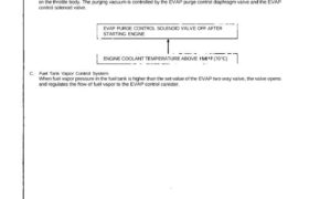
Emission Control System Description The evaporative emission controls are designed to minimize the amount of fuel vapor escaping to the atmosphere. The system consists of the following components: A. Evaporative Emission (EVAP) Control Canister An EVAP control canister is used for the temporary storage of fuel vapor until the fuel vapor can be purged from […]
Categories
nsxd11120a.pdf
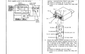
Fuel Supply System Description The PGM-FI main relay actually contains two individual relays. The relay is located behind the passenger’s seat back panel. One relay is energized whenever the ignition is on which supplies the battery voltage to the ECM, power to the fuel injectors, and power for the second relay. The second relay is […]
Categories
nsxe11104a.pdf
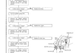
Fuel Supply System Main Relay (cont’d) Troubleshooting Flowchart Engine will not start. Inspection of main relay. Disconnect the main relay con- nectors. Measure the voltage between YEL/BLU terminal and body ground. Is there battery voltage? Replace ACG fuse. Turn the ignition switch ON. Measure the voltage between BLK/YEL terminal and body ground. Replace No. 2 […]
Categories
nsxb11121a.pdf
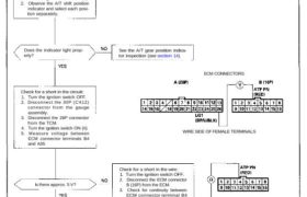
Inspection of A/T Gear Position Signal. This signals the ECM when the transmission is in position. Automatic Transaxle (A/T) Gear Position Signal Check the operation of the A/T gear position switch: 1. Turn the ignition switch ON (II). 2. Observe the A/T shift position indicator and select each posi- tion separately. Does the indicator light […]
Categories
nsxe11119a.pdf
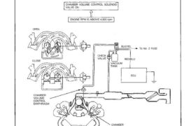
Chamber Volume Control System Description Satisfactory power performance is achieved by closing and opening the chamber volume control valves. High torque at low RPM is achieved when the valves are closed, whereas high power at high RPM is achieved by when the valves are opened. CHAMBER VOLUME CONTROL SOLENOID VALVE ON ENGINE RPM IS ABOVE […]
Categories
nsxe11112a.pdf
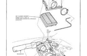
Air Intake System Air Cleaner Air Cleaner Element Replacement AIR CLEANER CASE AIR CLEANER ELEMENT Replace every 2 years of 30,000 miles (48,000 km), whichever comes first. AIR INTAKE DUCT RESONATOR Attachments nsxe11112a (105 kB)
Categories
nsxd11020a.pdf
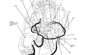
System Description System Connectors [Engine Compartment (Left Side)] ENGINE WIRE HARNESS C123 G103 C107 C106 ENGINE COMPARTMENT FUSE/RELAY BOX C108 C113 SIDE WIRE HARNESS C116 C532 C533 CONTROL BOX C534 C119 C121 C122 C106 C107 C108 C113 C116 C119 C533C532C121 C122 C123 C534 NOTE: Several different wires have the same color. They have been given […]
Categories
nsxb11024a.pdf
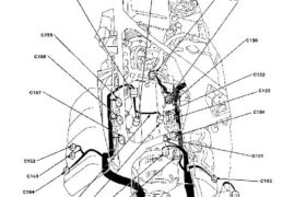
System Description System Connectors [Engine Compartment (Right Side)] Main Menu Table of Contents System Description System Connectors [Engine Compartment (Right Side)] C173 c159 c158 c132 c157 c133 c134 G101 c152 c153 c142 c154 KNOCK SENSOR c172 c145 HARNESS C156 C155 C151 C148 ENGINE WIRE HARNESS 11—24 NOTE: • Different wires with the same color have […]