Idle Control System
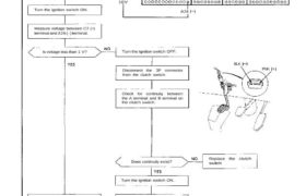
Troubleshooting Flowchart Clutch Switch Signal
This signals the PGM-FI ECU when the clutch is engaged.
Inspection of clutch switch
signal.
Connect the ECU test harness
between the ECU and connector
(page 11-21).
Less than 1 V?
10V
A26
C7
Turn the ignition switch ON.
Measure voltage between C7 (+)
terminal and A26 (-) terminal.
Is voltage less than 1 V? Turn the ignition switch OFF.
Disconnect the 3P connector
from the clutch switch.
BLK
PNK
Check for continuity between
the A terminal and B terminal on
the clutch switch.
Does continuity exist?
Replace the clutch
switch.
Turn the ignition switch ON.
Depress the clutch pedal.
Measure voltage between C7 (+)
terminal and A26 (-) terminal.
(To page 11-81)
Measure voltage between PNK
(+) terminal and body ground.
Is there approx. 10 V?
Repair open in BLK wire be-
tween the clutch switch and
G401.
Repair open in PNK
wire between ECU
(C7) and the clutch
switch.
(From page 11-80)
Is there approx. 10V?
Clutch switch signal is OK.
Turn the ignition switch OFF.
Disconnect the 3P connector
from the clutch switch.
Turn the ignition switch ON.
Measure voltage between C7 (+)
terminal and A26 (-) terminal
with the clutch pedal depressed.
Is there approx. 10V?
Replace the clutch
switch.
Turn the ignition switch OFF.
Disconnect “C” connector from
engine wire harness only, not the
ECU.
Turn the ignition switch ON.
Is there approx. 10V?
Repair short in PNK
wire between ECU
(C7) and the clutch
switch.
Substitute a known-good ECU
and recheck. If prescribed
voltage is now available, replace
the original ECU.