Category: Fuel & Emissions
Categories
nsxd11043a.pdf
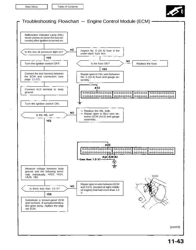
Troubleshooting Flowchart Engine Control Module (ECM) Malfunction Indicator Lamp (MIL) never comes on (even for two se- conds) after ignition is turned on. Is the low oil pressure light on? Turn the ignition switch OFF. Connect the test harness between the ECM and connectors (see page 11-37). Connect A13 terminal to body ground. Turn the […]
Categories
nsxd11085a.pdf
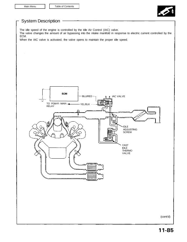
System Description The idle speed of the engine is controlled by the Idle Air Control (IAC) valve. The valve changes the amount of air bypassing into the intake manifold in response to electric current controlled by the ECM. When the IAC valve is activated, the valve opens to maintain the proper idle speed. (cont’d) IDLE […]
Categories
nsxd11143a.pdf
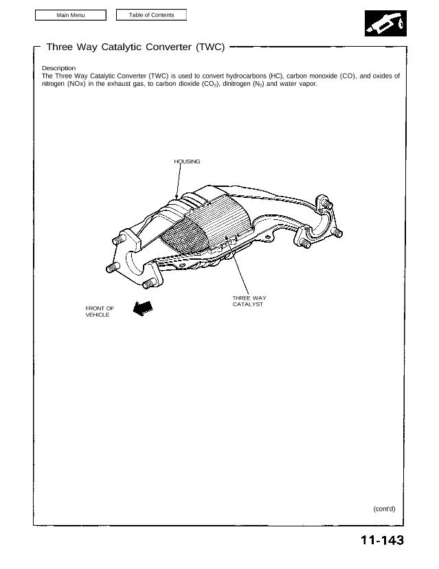
Three Way Catalytic Converter (TWC) Description The Three Way Catalytic Converter (TWC) is used to convert hydrocarbons (HC), carbon monoxide (CO), and oxides of nitrogen (NOx) in the exhaust gas, to carbon dioxide (CO2), dinitrogen (N2) and water vapor. HOUSING THREE WAY CATALYST FRONT OF VEHICLE (cont’d) Attachments nsxd11143a (167 kB)
Categories
nsxe11082a.pdf
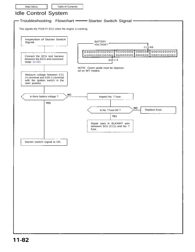
Idle Control System Troubleshooting Flowchart Starter Switch Signal This signals the PGM-FI ECU when the engine is cranking. Inspection of Starter Switch Signal. BATTERY VOLTAGE? C 11 A26 NOTE: Clutch pedal must be depress- ed on M/T models. Connect the ECU test harness between the ECU and connector (page 11-21). Measure voltage between C11 (+) […]
Categories
nsxb11026a.pdf
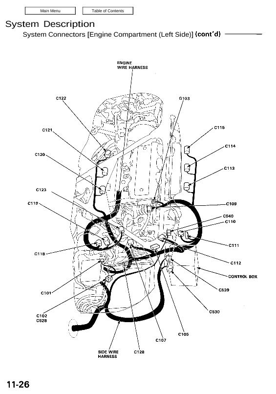
System Description System Connectors [Engine Compartment (Left Side)] Main Menu Table of Contents System Description System Connectors [Engine Compartment (Left Side)] (cont’d) ENGWE WIRE HARNESS C120 J» / −↗⋯ it c123 _ ∣ ∁↿↿∍ più” ⋡↽≓≓ C109 ∙ c540 A r` c110 I 0″” _ O `v c111 ↽ ≓−⇖⋅⋅⋡ X ∎ ∖↜∖ c113 ‚_— […]
Categories
nsxb11038a.pdf
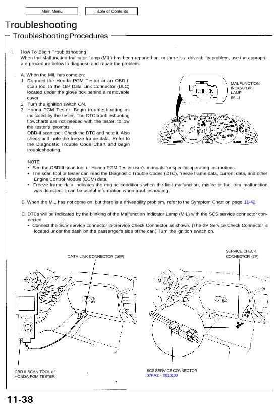
Troubleshooting Troubleshooting Procedures I. How To Begin Troubleshooting When the Malfunction Indicator Lamp (MIL) has been reported on, or there is a driveability problem, use the appropri- ate procedure below to diagnose and repair the problem. MALFUNCTION INDICATOR LAMP (MIL) A. When the MIL has come on: 1. Connect the Honda PGM Tester or an […]
Categories
nsxe11002a.pdf
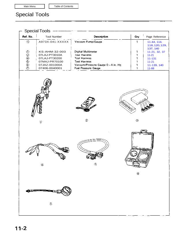
Special Tools Special Tools Page Reference 11-44, 114, 118, 120, 129, 137, 140 11-21, 32, 37 11-21 11-131 11-21 11-139, 140 11-88 Tool Number A973X-041-XXXXX KS-AHM-32-003 07LAJ-PT3010A 07LAJ-PT30200 07MAJ-PR70100 07JAZ-001000A 07406-0040001 Main Menu Table of Contents Special Tools — Special Tools Ref. No. Tool Number Description Qty Page Reference ® A973X—041—XXXXX Vacuum Pump/Gauge 1 11-44, […]
Categories
nsxb11107a.pdf
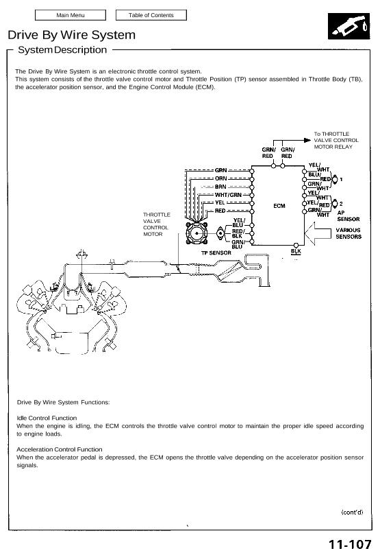
Drive By Wire System System Description The Drive By Wire System is an electronic throttle control system. This system consists of the throttle valve control motor and Throttle Position (TP) sensor assembled in Throttle Body (TB), the accelerator position sensor, and the Engine Control Module (ECM). To THROTTLE VALVE CONTROL MOTOR RELAY THROTTLE VALVE CONTROL […]
Categories
nsxb11059a.pdf
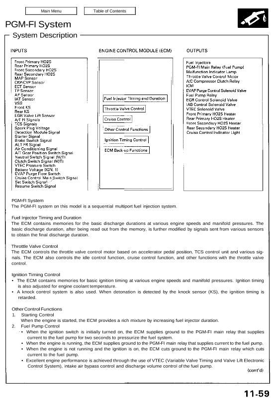
PGM-FI System System Description PGM-FI System The PGM-FI system on this model is a sequential multiport fuel injection system. Fuel Injector Timing and Duration The ECM contains memories for the basic discharge durations at various engine speeds and manifold pressures. The basic discharge duration, after being read out from the memory, is further modified by […]
Categories
nsxb11134a.pdf
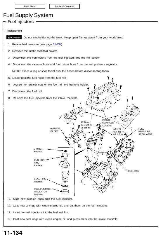
Fuel Supply System Fuel Injectors Replacement Do not smoke during the work. Keep open flames away from your work area. 1. Relieve fuel pressure (see page 11-132). 2. Remove the intake manifold covers. 3. Disconnect the connectors from the fuel injectors and the IAT sensor. 4. Disconnect the vacuum hose and fuel return hose from […]