Category: Fuel & Emissions
Categories
nsxd11102a.pdf
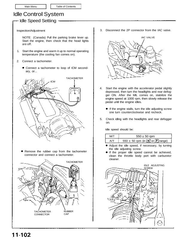
Idle Control System Idle Speed Setting Inspection/Adjustment NOTE: (Canada) Pull the parking brake lever up. Start the engine, then check that the head lights are off. 1. Start the engine and warm it up to normal operating temperature (the cooling fan comes on). 2. Connect a tachometer. Connect a tachometer to loop of ICM second- […]
Categories
nsxb11132b.pdf
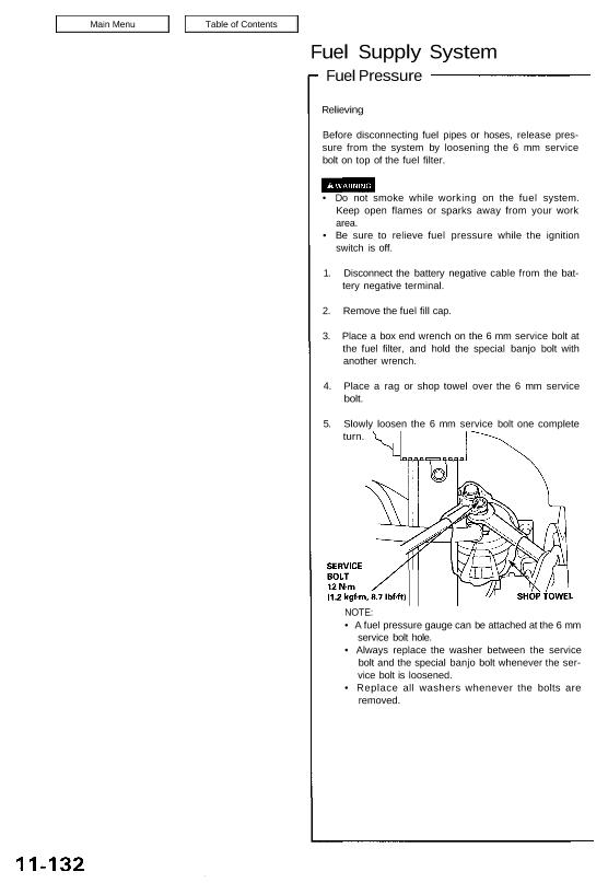
Fuel Supply System Fuel Pressure Relieving Before disconnecting fuel pipes or hoses, release pres- sure from the system by loosening the 6 mm service bolt on top of the fuel filter. • Do not smoke while working on the fuel system. Keep open flames or sparks away from your work area. • Be sure to […]
Categories
nsxd11044a.pdf
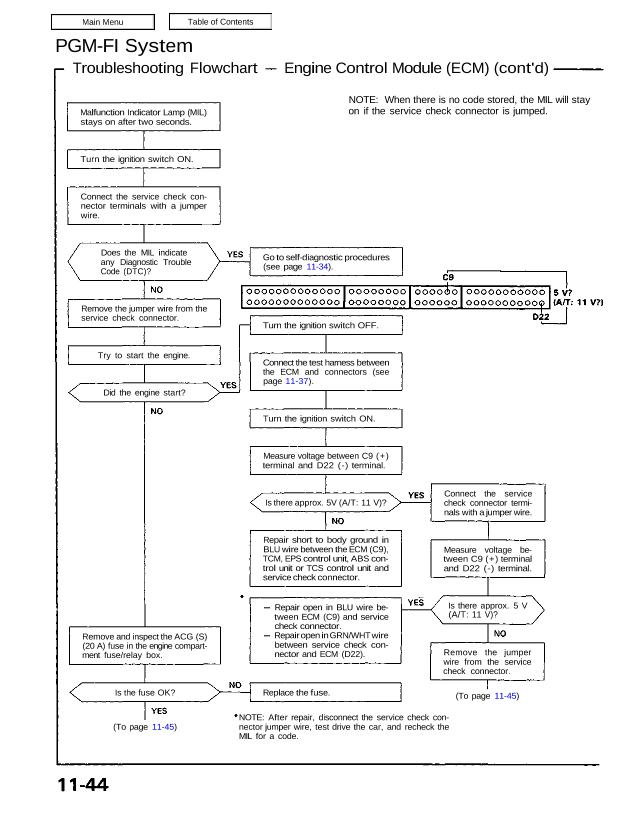
PGM-FI System Troubleshooting Flowchart Engine Control Module (ECM) (cont’d) Malfunction Indicator Lamp (MIL) stays on after two seconds. Turn the ignition switch ON. Connect the service check con- nector terminals with a jumper wire. Does the MIL indicate any Diagnostic Trouble Code (DTC)? Remove the jumper wire from the service check connector. Try to start […]
Categories
nsxe11140a.pdf
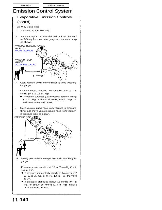
Emission Control System Evaporative Emission Controls (cont’d) Two-Way Valve Test 1. Remove the fuel filler cap. 2. Remove vapor line from the fuel tank and connect to T-fitting from vacuum gauge and vacuum pump as shown. VACUUM/PRESSURE GAUGE 0-4 in. Hg 07JAZ–001000A VACUUM PUMP/ GAUGE A973X–041–XXXXX T—FITTING 3. Apply vacuum slowly and continuously while watching […]
Categories
nsxe11087a.pdf
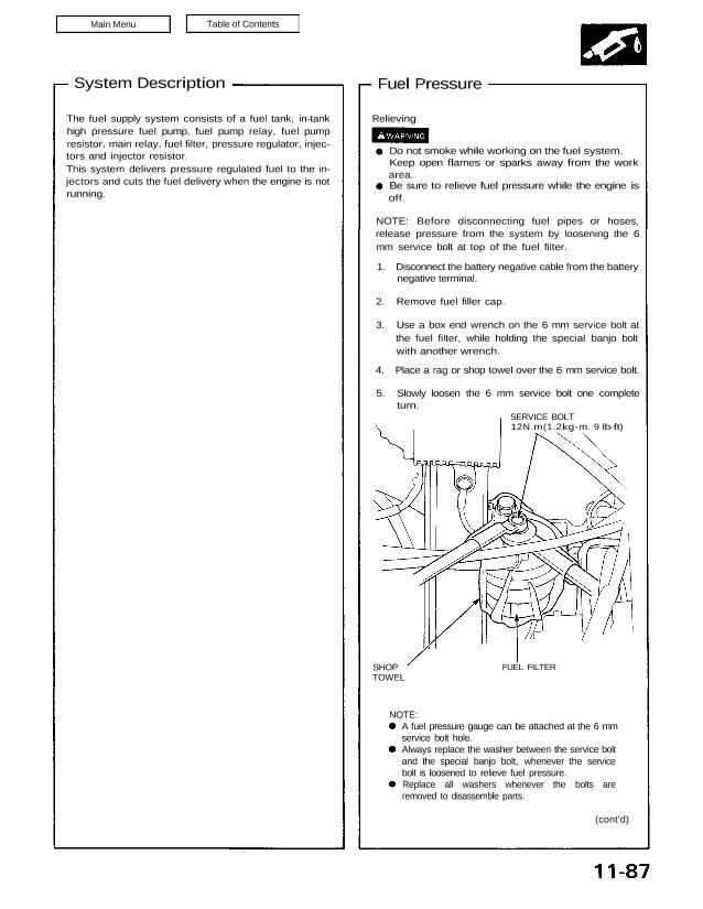
System Description Fuel Pressure The fuel supply system consists of a fuel tank, in-tank high pressure fuel pump, fuel pump relay, fuel pump resistor, main relay, fuel filter, pressure regulator, injec- tors and injector resistor. This system delivers pressure regulated fuel to the in- jectors and cuts the fuel delivery when the engine is not […]
Categories
nsxe11137a.pdf
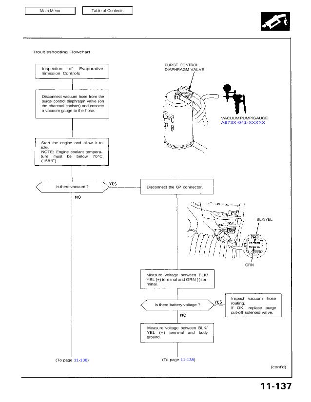
Troubleshooting Flowchart Inspection of Evaporative Emission Controls PURGE CONTROL DIAPHRAGM VALVE VACUUM PUMP/GAUGE A973X-041-XXXXX Disconnect vacuum hose from the purge control diaphragm valve (on the charcoal canister) and connect a vacuum gauge to the hose. Start the engine and allow it to idle. NOTE: Engine coolant tempera- ture must be below 70°C (158°F). Is there […]
Categories
nsxd11105b.pdf
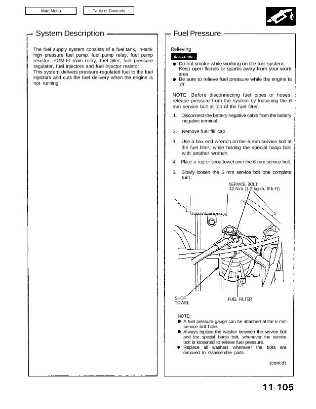
System Description The fuel supply system consists of a fuel tank, in-tank high pressure fuel pump, fuel pump relay, fuel pump resistor, PGM-FI main relay, fuel filter, fuel pressure regulator, fuel injectors and fuel injector resistor. This system delivers pressure-regulated fuel to the fuel injectors and cuts the fuel delivery when the engine is not […]
Categories
nsxd11090a.pdf
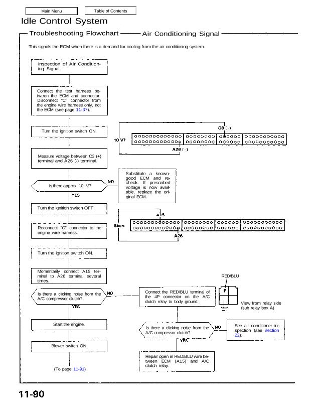
Idle Control System Troubleshooting Flowchart Air Conditioning Signal This signals the ECM when there is a demand for cooling from the air conditioning system. Inspection of Air Condition- ing Signal. Connect the test harness be- tween the ECM and connector. Disconnect “C” connector from the engine wire harness only, not the ECM (see page 11-37). […]
Categories
nsxd11151a.pdf
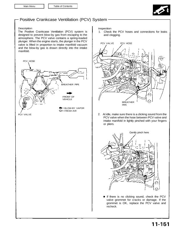
Positive Crankcase Ventilation (PCV) System Description The Positive Crankcase Ventilation (PCV) system is designed to prevent blow-by gas from escaping to the atmosphere. The PCV valve contains a spring-loaded plunger. When the engine starts, the plunger in the PCV valve is lifted in proportion to intake manifold vacuum and the blow-by gas is drawn directly […]
Categories
nsxb11148a.pdf
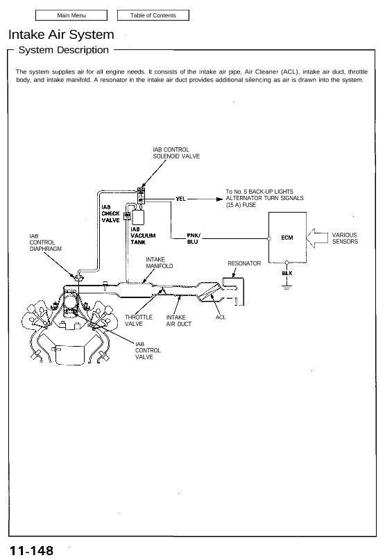
Intake Air System System Description The system supplies air for all engine needs. It consists of the intake air pipe, Air Cleaner (ACL), intake air duct, throttle body, and intake manifold. A resonator in the intake air duct provides additional silencing as air is drawn into the system. IAB CONTROL SOLENOID VALVE To No. 5 […]