Category: Cylinder Head & Valve Train
nsxb06031a.pdf
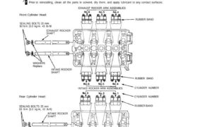
Locations CAUTION: After installing the rocker shaft orifice, try to turn the rocker shaft to make sure that the orifice has been inserted In the hole of the rocker shaft correctly- If the orifice is in place, it should not turn. NOTE: Identify parts as they are removed to ensure reinstallation in priginal locations. Inspect […]
nsxd06044a.pdf
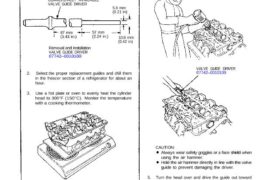
4. Working from the camshaft side, use the driver and an air hammer to drive the guide about 2 mm towards the combustion chamber. This will knock off some of the carbon and make removal easier. VALVE GUIDE DRIVER 07742–0010100 5. Turn the head over and drive the guide out toward the camshaft side of […]
nsxb06040a.pdf
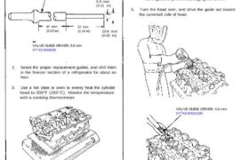
Valve Guides Replacement 1. As illustrated below, use a commercially – available air-impact valve guide driver attachment modified to fit the diameter of the valve guides. In most cases, the same procedure can be done using the special tool and a conventional hammer. IMPACT VALVE GUIDE DRIVER (Commercially available) 5.3 mm (0.21 in) 87 mm […]
nsxb06002a.pdf
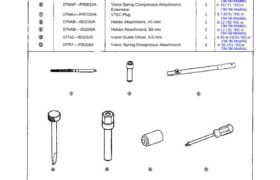
Special Tools Ref. No. Tool Number 07HAH—-PJ7010B 07JAA—001020A 07JAB—001020A 07MAA—PR70110 07MAA—PR70120 07MAF—PR9010A 07MAJ—PR7020A 07NAB—001030A 07NAB — 001040A 07742—0010100 07757—-PJ1010A Description Valve Guide Reamer, 5.5 mm Socket, 19 mm Holder Handle Tappet Adjuster Tappet Locknut Wrench Valve Spring Compressor Attachment Extension VTEC Plug Holder Attachment, 45 mm Holder Attachment, 50 mm Valve Guide Driver, 5.5 mm […]
nsxd06046a.pdf
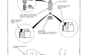
Valves, Valve Springs and Valve Seals Valve Spring and Valve Seal Installation Sequence NOTE: Exhaust and intake valve seals are NOT interchangeable. INTAKE VALVE SPRING NOTE: Place the end of valve spring with closely wound coils toward the cylinder head. INTAKE VALVE SEAL (WHITE SPRING) Replace. VALVE SEAL INSTALLER KD-2899 VALVE SEAL Replace. VALVE KEEPERS […]
nsxd06041a.pdf
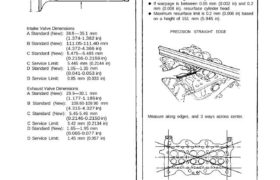
Intake Valve Dimensions A Standard (New): 34.9 — 35.1 mm (1.374-1.382 in) B Standard (New): 111.05-111.40 mm (4.372-4.386 in) C Standard (New): 5.475—5.485 mm (0.2156-0.2159 in) C Service Limit: 5.445 mm (0.2144 in) D Standard (New): 1.05—1.35 mm (0.041-0.053 in) D Service Limit: 0.85 mm (0.033 in) Exhaust Valve Dimensions A Standard (New): 29.9—30.1 mm […]
nsxb06006a.pdf
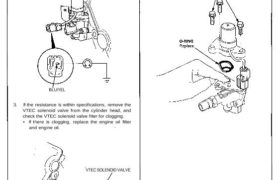
VTEC VTEC Solenoid Valve Inspection 1. Disconnect the 2P connector from the VTEC sole- noid valve. 2. Measure resistance between the BLU/YEL (front/rear) terminals and body ground. Resistance: approx 14 – 30 ohms BLU/YEL 3. If the resistance is within specifications, remove the VTEC solenoid valve from the cylinder head, and check the VTEC solenoid […]
nsxd06021a.pdf
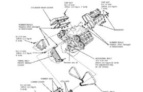
Remove any oil. TIMING BELT Inspection, page 6-22 Adjustment, page 6-22 6 x 1.0 mm 12N.m(1.2kg-m,9 Ib-ft) Timing Belt Illustrated Index Turn the crankshaft so that the No. 1 piston is at top dead center (TDC) (page 6-25, 26) Replace rubber seals if damaged or deteriorated. Prior to installing the cylinder head cover, apply a […]
nsxd06037a.pdf
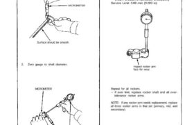
Rocker Arms and Shafts Clearance Measure both the intake rocker shafts and exhaust rocker shafts. 1. Measure diameter of shaft at first rocker location. MICROMETER Surface should be smooth. 2. Zero gauge to shaft diameter. MICROMETER CYLINDER BORE GAUGE Inspect rocker arm face for wear. Repeat for all rockers. 3. Measure inside diameter of rocker […]
nsxb06045b.pdf
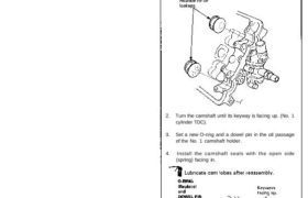
Camshafts Installation CAUTION: Valve locknuts should be loosened and ad- justing screws backed off before installation. 1. After wiping down the camshaft and journals in the cylinder head, lubricate both surfaces and install the camshafts and rubber caps. NOTE: Apply liquid gasket around the rubber cap. 2. Turn the camshaft until its keyway is facing […]