Installation
CAUTION: Valve locknuts should be loosened and ad-
justing screws backed off before installation.
1. After wiping down the camshaft and journals in the
cylinder head, lubricate both surfaces and install the
camshafts and rubber caps.
NOTE: Apply liquid gasket around the rubber cap.
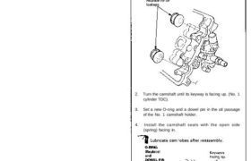
2. Turn the camshaft until its keyway is facing up. (No. 1
cylinder TDC).
3. Set a new O-ring and a dowel pin in the oil passage
of the No. 1 camshaft holder.
4. Install the camshaft seals with the open side
(spring) facing in.
Camshafts
Installation
5. Apply liquid gasket to the head mating surfaces of
the No. 1 and the No. 4 camshaft holders.
– Apply liquid gasket to the shaded areas.
6. Install the camshaft holders.
NOTE:
• “F” or “R” marks are stamped on the camshaft
holders.
• The arrows must be pointing to the timing belt
side.
• Set two dowel pins in each camshaft holder.
FRONT:
No. 4 No. 3 No. 2 No. 1
CAMSHAFT CAMSHAFT CAMSHAFT CAMSHAFT
HOLDER HOLDER HOLDER HOLDER
REAR:
No. 4 No. 3 No. 2 No. 1
CAMSHAFT CAMSHAFT CAMSHAFT CAMSHAFT
HOLDER HOLDER HOLDER HOLDER
7. Install the camshaft holder plates.
8. Tighten each bolt two turns at a time in the sequence
shown below to insure that the rockers do not bind
on the valves.
NOTE: Apply clean engine oil to 8 mm bolt threads.
Specified torque:
8 mm x 1.25 mm bolts:
22 N-m (2.2 kg-m, 16 Ib-ft)
6 mm x 1.0 mm bolts:
10 N-m (1.0 kg-m, 7 Ib-ft)
CAMSHAFT HOLDER BOLT TORQUE SEQUENCE
FRONT:
9. Install the CKP/CYP sensor on the front cylinder
head.
CKP/CYP SENSOR
6 x 1.0 mm
12 N·m (1.2 kg-m, 9 Ib-ft)
10. Install the front and rear back covers.
RUBBER SEALS
REAR BACK COVER
6 x 1.0 mm
12 N·m (1.2 kg-m,
9 Ib-ft)
RUBBER SEALS
FRONT BACK COVER
RUBBER SEAL
11. Insert the dowel pins in the camshaft pulley.
12. Install the camshaft pulleys, then tighten the retain-
ing bolts to the torque specified.
CAMSHAFT PULLEYS
13. Install the timing belt (see page 6-18 (’91-’93) or (’94-’96)) .
14. Adjust the valve clearance (see page 6-9 (’91-’93) or (’94-’96)).
15. Inspect the rocker arms (see pages 6-7(’91-’93) or (’94-’96),
8 (’91-’93) or (’94-’96)).
16. Install the head cover gasket in the groove of the
cylinder head cover. Seat the recesses for the
camshaft first, then work it into the groove around
the outside edges.
NOTE:
Before installing the head cover gasket, thor-
oughly clean the seal and the groove.
When installing, make sure the head cover gasket
is seated securely in the corners of the recesses
with no gap.
HEAD COVER
GASKET
Clean.
RUBBER
SEAL
CORNERS OF
THE RECESSES
CYLINDER HEAD
COVER
CORNERS OF
THE RECESSES (cont’d)
RETAINING BOLTS
10 x 1.25 mm
70 N·m (7.0 kg-m, 51 Ib-ft)
Camshafts
Installation
17. Apply liquid gasket to the head cover gasket at the
eight corners of the recesses.
NOTE:
• Use liquid gasket, Part No. 08718-0001.
• Check that the mating surfaces are clean and dry
before applying liquid gasket.
• Do not install the parts if five minutes or more
have elapsed since applying liquid gasket. Instead,
reapply liquid gasket after removing old residue.
• After assembly, wait at least 20 minutes before
filling the engine with oil.
Apply liquid gasket to
the shaded areas.
18. When installing the cylinder head cover, hold the
head cover gasket in the groove by placing your fin-
gers on the camshaft contacting surfaces (top of the
semicircles).
Once the cylinder head cover is on the cylinder
head, slide the cover slightly back and forth to seat
the head cover gasket.
NOTE:
• Before installing the cylinder head cover, clean
the cylinder head contacting surfaces with a
shop towel.
• Do not touch the parts where liquid gasket was
applied.
• Replace the washer when damaged or deterio-
rated.
WASHER
CYLINDER
HEAD COVER
6 x 1.0 mm
12 N-m (1.2 kg-m,
9 Ib-ft)
19. Tighten the nuts in two or three steps. In the final step,
tighten all nuts, in sequence, to 12 N-m (1.2 kg-m,
9 Ib-ft).
NOTE: After assembly, wait at least 20 minutes
before filling the engine with oil.
20. After installation, check that all tubes, hoses and
connectors are installed correctly.
NOTE: After installation, fill the engine with oil up to
the specified level, run the engine for more than three
minutes, then check for oil leakage.