Removal
Make sure jacks and safety stands are placed properly
and hoist brackets are attached to the correct posi-
tions on the engine (see section 1).
• Make sure the car will not roll off stands and fall
while you are working under it.
CAUTION:
• Use a fender cover (special tool) to avoid damaging
painted surfaces.
• Unspecified items are common.
• Unplug the wiring connectors carefully while holding
the connector portion to avoid damage.
• Mark all wiring and hoses to avoid misconnection.
Also, be sure that they do not contact other wiring or
hoses or interfere with other parts.
• If the ground clearance needs to be increased, use a
scissors jack and install rubber spacers in the coil
springs (see section 1).
• Put rubber pads under the jacking points when using
jacks or safety stands to avoid damaging the body
(see section 1).
1. Move the seat bottoms and backs as far forward as
they will go.
2. Remove the rear hatch assembly and engine cover
(see section 20).
3. Disconnect the battery negative terminal first, then
the positive terminal.
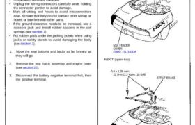
4. Remove the strut brace.
COUPE:
STRUT BRACE
8 x 1.25 mm
22 N-m (2.2 kg-m,
16 Ib-ft)
NSX FENDER
COVER
07MAZ – SLOOOOA
NSX-T (open top):
8 x 1.25 mm
22 N-m (2.2 kg-m, 16 Ib-ft)
STRUT BRACE
NSX FENDER COVER
07MAZ-SLOOOOA
CORROSION RESISTANT BOLT
Engine Removal/Installation
Removal
5. Disconnect the fan motor connector, then remove
the engine room fan assembly.
ENGINE ROOM
FAN
FAN MOTOR
CONNECTOR
6 x 1.0 mm
10 N-m (1.0 kg-m, 7 Ib-ft)
6. Remove the rear trim panels behind the passenger’s
seat, then disconnect four connectors from the
engine control module (ECM) and three connectors
from the floor wire harness.
ENGINE WIRE
HARNESS
ECM
FLOOR WIRE
HARNESS
CORROSION RESISTANT BOLT
7. Disconnect the spark plug voltage detection module
connectors, ground cable and engine wire harness
clamps.
SPARK PLUG VOLTAGE
DETECTION MODULE
CONNECTORS
GROUND
CABLE
ENGINE WIRE
HARNESS CLAMPS
8. Disconnect the fuel pump resistor connector, injec-
tor resistor connector and ground cable.
FUEL PUMP RESISTOR
CONNECTOR
GROUND CABLE
INJECTOR RESISTOR
CONNECTOR
9. Relieve fuel pressure by loosening the service bolt
on the fuel filter about one turn (see section 11).
Do not smoke while working on the
fuel s y s t e m . Keep open flame away from work
area. Drain fuel only into an approved container.
10. Remove the fuel feed pipe and fuel return hose.
11. Remove the wire harness cover, then remove the
fuel pipe clamp.
22 N·m (2.2 kg-m,
16 Ib-ft) WIRE HARNESS
COVER
6 x 1.0 mm
12 N·m (1.2 kg-m,
9 lb-ft)
FUEL FEED
PIPE
WASHERS
Replace.
FUEL RETURN
HOSE
12. Remove the brake booster vacuum hose and evapo-
rative emission (EVAP) control canister hose.
BRAKE BOOSTER
VACUUM HOSE
EVAP CONTROL
CANISTER HOSE
13. Remove the expansion tank cap.
14. Raise the hoist to full height.
15. Drain the engine coolant (see page 10-5).
Loosen the drain plug from the radiator lower
tank.
Remove two drain bolls from the water pipes.
Reinstall the drain bolts with new washers.
Loosen the front and rear engine drain bolts to
drain engine coolant from the cylinder heads.
Connect rubber hoses to the drain bolts.
16. Drain the transmission oil/fluid. Reinstall the drain
plug with a new washer.
17. Drain the engine oil. Reinstall the drain plug with a
new washer.
18. Lower the hoist, then remove the air cleaner hous-
ing (see page 6-25 (’91-’93 Models),or(’95-’96 Models).
19. Disconnect two hoses, then remove the expansion
tank.
6 x 1.0 mm
10 N·m 11.0 kg-m,
7 lb-ft) EXPANSION
TANK
WATER BYPASS
HOSES
(cont’d)
Engine Removal/Installation
Removal
20. Disconnect the engine wire harness connectors.
21. Remove the battery cable from the main fuse box.
ENGINE WIRE
HARNESS CONNECTORS
BATTERY
CABLE
6 x 1.0 mm
10 N-m (1.0 kg-m,
7 Ib-ft)
22. Disconnect the throttle body 6P connector, and
remove the ground cable and starter cable.
STARTER CABLE
THROTTLE BODY
6P CONNECTOR
GROUND CABLE
CORROSION RESISTANT BOLT
23. Disconnect the two connectors from the emission
control box, then remove the control box.
• Do not disconnect the vacuum hoses.
6 x 1.0 mm
10 N-m (1.0 kg-m, 7 Ib-ft)
CONNECTORS
CONTROL BOX
24. Remove the radiator hoses and heater hose.
HEATER HOSE
RADIATOR
HOSES
25. Loosen the idler pulley center nut and adjusting nut,
then remove the air conditioning (A/C) compressor
belt.
ADJUSTING
NUT
A/C COMPRESSOR
BELT
IDLER PULLEY
CENTER NUT
45 N-m (4.5 kg-m,
33 Ib-ft)
26. Move the trunk carpet, and disconnect the right rear
wheel sensor connector. Push the wire and connec-
tor through the body hole into the engine compart-
ment.
RIGHT REAR SENSOR
CONNECTOR
27. Raise the hoist to full height.
28. Remove the slave cylinder (M/T see section 12).
• Do not disconnect the clutch hose.
29. Remove the lower cover, then remove the shift
cable and select cable (M/T see section 13).
30. Remove the cable cover, then remove the shift
cable (A/T).
NOTE:
• Take care not to bend the cable when removing
it. Always replace a kinked cable with a new one.
• Adjust the cable when installing.
31. Remove the engine under guard and the center rod
assembly.
A/T:
CONTROL LEVER
CENTER ROD
ASSEMBLY
8 x 1.25 mm
22 N-m (2.2 kg-m,
16 Ib-ft)
6 x 1.0 mm
8 N-m (0.8 kg-m, 6 Ib-ft)
6 x 1.0 mm
12 N-m (1.2 kg-m, 9 Ib-ft)
UNDER GUARD
10 x 1.25 mm
60 N-m (6.0 kg-m, 43 Ib-ft)
SHIFT CABLE
CABLE COVER
Engine Removal/Installation
Removal
32. Remove the left and right parking brake cables (see
section 19).
33. Remove the rear beam rod assembly and parking
brake cable clamps. ‘
10 x 1.25 mm
60 N-m (6.0 kg-m,
43 Ib-ft)
12 x 1.25 mm
95 N-m (9.5 kg-m,
69 Ib-ft)
34. Remove the front engine mount, then remove the
front beam.
12 x 1.25 mm
77 N-m (7.7 kg-m, 56 Ib-ft)
Replace.
12 x 1.25 mm-
95 N-m (9.5 kg-m,
69 Ib-ft)
CORROSION RESISTANT BOLT/NUT
35. Remove the A/C compressor (see section 22), then
suspend it from the body.
NOTE:
• Do not remove the compressor hoses.
• Do not let the compressor hang by its hoses.
36. Reinstall the front beam and front engine mount.
Hang with wire
or rope.
A/C COMPRESSOR
37. Remove the rear brake hoses, then plug the brake
pipes with rubber caps (see section 19).
38. Disconnect the left rear wheel sensor connector,
then remove the wheel sensor wire clamps and sta-
bilizer link.
6 x 1.0 mm
10 N-m (1.0 kg-m,
7 Ib-ft)
LEFT REAR
WHEEL SENSOR
CONNECTOR
SELF-LOCKING NUT
12 x 1.25 mm
95 N-m (9.5 kg-m,
69 Ib-ft)
Replace.
STABILIZER
LINK SELF-LOCKING NUT12 x 1.25 mm
85 N-m (8.5 kg-m, 62 Ib-ft)
Replace.
REAR BEAM
ROD ASSEMBLY
39. Remove the right wheel sensor wire clamps and
stabilizer link.
6 x 1.0 mm
10 N-m (1.0 kg-m,
7 Ib-ft)
STABILIZER
LINK
SELF-LOCKING NUT
12 x 1.25 mm
95 N-m (9.5 kg-m,
69 Ib-ft)
Replace.
SELF-LOCKING NUT
12 x 1.25 mm
85 N-m (8.5 kg-m, 62 Ib-ft)
Replace.
40. Disconnect the front secondary heated oxygen sensor
connector, then remove the front exhaust pipe A and
front three way catalytic converter (TWC).
41. Separate the rear TWC from the rear joint pipe.
SELF-LOCKING NUTS
10 x 1.25 mm
34 N-m (3.4 kg-m, 25 Ib-ft)
Replace.
GASKETS
Replace.
GASKET
Replace. SELF-LOCKING NUT •
10 x 1.25 mm
55 N-m (5.5 kg-m, 40 Ib-ft)
Replace.
42. Position the special tool under the car. Lower the car
just above the fixture. With the help of an assistant,
attach the fixture to the subframe with two 12 mm
nuts and two 10 mm bolts.
LOOSELY INSTALL TWO 12 mm
NUTS ON STUDS HERE
ENGINE REMOVAL/
INSTALLATION
FIXTURE
07MAK-PR7020A
LOOSELY INSTALL ONE
10 mm BOLT HERE
43. Adjust the pads on the fixture to support the oil pan
and transmission housing.
44. Lower the car so the fixture is resting on its casters
(or appropriate platform).
45. Remove the two bolts from the side engine mount
near the alternator. Pivot the mounting bracket into
the housing of the body.
BODY SUPPORT
BRACKET
SIDE ENGINE
MOUNT
Engine Removal/Installation
Removal
46. Remove the transmission mounting bolt.
MOUNTING BOLT
TRANSMISSION
MOUNT
47. Remove the twelve subframe-to-body mounting
bolts.
48. Raise the car a few inches.
49. Check that all wires and hoses are disconnected
from the engine assembly.
50. Raise the car completely off the engine/suspension
assembly. Roll the assembly from under the car.
NOTE: Perform steps 51 thru 54 only if the engine
assembly is to be removed from the subframe.
51. Remove the adjusting bolt and flange bolt, then
separate the lower control arm from the subframe
(see section 18).
52. Remove the flange bolt, then separate the toe control
arm from the subframe (see section 18).
CAUTION: Make sure that the reference marks on
the control arm are aligned.
53. Remove the heat shield form the intermediate shaft
bearing support, then remove the driveshafts (see
section 16).
NOTE:
• Coat all precision finished surfaces with clean
engine oil.
• Tie plastic bags over the driveshaft ends.
54. Attach a chain hoist to the engine.
Remove the front and rear mount mounting bolts,
then separate the engine from the suspension and
the beam assembly.
CAUTION: Do not hit the engine oil cooler on the
rear right beam bracket.
FRONT MOUNT
REAR MOUNT