Category: Electrical
Categories
nsxb23245a.pdf
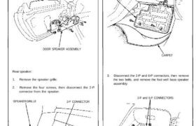
Front/Rear Speaker Replacement Front speaker: 1. Remove the door panel (see section 20). 2. Remove the door speaker assembly from the door panel by removing the five screws. DOOR SPEAKER ASSEMBLY Rear speaker: 1. Remove the speaker grille. 2. Remove the four screws, then disconnect the 2-P connector from the speaker. SPEAKER GRILLE 2-P CONNECTOR […]
Categories
nsxd23106a.pdf
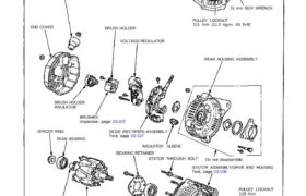
Charging System Alternator Overhaul NOTE: It is only necessary to separate the pulley, drive end housing and rotor when the front bearing needs replacement. Loosen the locknut with 10 mm and 22 mm wrenches to remove the pulley from the rotor. If necessary, use an impact wrench. TERMINAL INSULATOR END COVER BRUSH HOLDER 22 mm […]
Categories
nsxb23284a.pdf
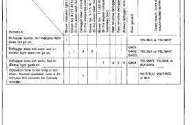
Troubleshooting Rear Window Defogger NOTE: The numbers in the table show the troubleshooting sequence. Main Menu Table of Contents Rear Window Defogger Troubleshooting NOTE: The numbers in the table show the troubleshooting sequence. Item to be inspected ↩ VI Ф ↩ ⊏ ≡ _ .g a ä ä ë š E aa’o ⊏−∘ fin .2E […]
Categories
nsxb23119a.pdf
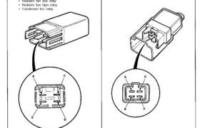
Fan Relay Tests Check continuity at the relay terminals. • There should be continuity between the C and D ter- minals. • There should be continuity between the A and B ter- minals when power and ground are connected to the C and D terminals. • There should be no continuity between the A and […]
Categories
nsxb23276a.pdf
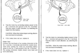
Power Windows Driver’s Motor Test Motor Test: 1. Remove the door panel (see section 20). 2. Disconnect the 4-P connector from the driver’s motor. View from wire side 3. Test the motor by connecting battery power to the No. 4 terminal and ground to the No. 3 terminal. Test the motor in each direction, by […]
Categories
nsxd23091a.pdf
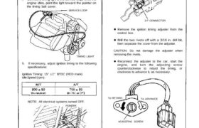
Ignition Timing Inspection and Setting 1. Start the engine and allow it to warm up (radiator fan comes on). 2. Pull out the service check connector located under the middle of the dash. Connector the BLU and GRN/WHT terminals with a jumper wire (see sec- tion 11). 3. Check the idle speed (see page 23-92). […]
Categories
nsxb23128a.pdf
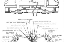
Gauge Assembly Bulb Locations GAUGE LIGHTS (1.4W x 2) SRS INDICATOR LIGHT (1.4 W) RIGHT TURN SIGNAL INDICATOR LIGHT (1.4 W) EPS INDICATOR LIGHT (1.4 W) BRAKE SYSTEM LIGHT (1.4 W) SEAT BELT REMINDER LIGHT (1.4 W) TCS INDICATOR LIGHT (1.96 W) LOW FUEL INDICATOR LIGHT (1.4 W) GAUGE LIGHT (1.4 W) HIGH BEAM INDICATOR […]
Categories
nsxb23118a.pdf
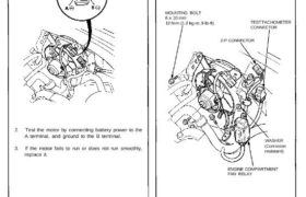
Radiator and Condenser Fan Controls Engine Compartment Fan Motor Test (A/T) 1. Disconnect the 2-P connector from the engine compartment fan motor. 2. Test the motor by connecting battery power to the A terminal, and ground to the B terminal. 3. If the motor fails to run or does not run smoothly, replace it. Engine […]
Categories
nsxe23148a.pdf
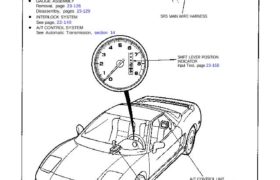
Shift Lever Position Indicator CAUTION: All SRS electrical wiring harnesses are covered with yellow outer insulation. Before disconnecting the SRS wire harness, install the short connector on the airbag (see page STET) Replace the entire affected SRS harness assembly if it has an open circuit or damaged wiring. After installation of the gauge assembly, recheck […]
Categories
nsxe23068a.pdf
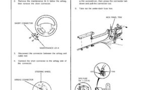
Under-Dash Fuse Box Removal/Installation CAUTION; Be sure to install the SRS wiring so that it is not pinched or interfering with other car parts. Always keep the short connector on the airbag con- nector when the harness is disconnected. Removal: 1. Disconnect both the negative cable and positive ca- ble from the battery. 2. Remove […]