Category: Electrical
Categories
nsxd23279a.pdf
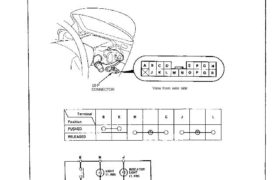
Switch Test 1. Remove the dashboard lower cover. 2. If necessary, remove the knee bolster. 3. Disconnect the 18-P connector from the floor wire harness. 4. Check for continuity between the terminals in each switch position according to the table. 18-P CONNECTOR View from wire side Attachments nsxd23279a (142 kB)
Categories
nsxb23133a.pdf
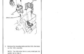
Vehicle Speed Sensor (VSS) Replacement 1. Disconnect the 3-P connector from the vehicle speed sensor (VSS). 3-P CONNECTOR MOUNTING BOLTS 2. Remove the mounting bolts and the VSS, then take out the VSS assembly. NOTE: The VSS drive link is a very small part, be careful not to lose it. 3. Install in the reverse […]
Categories
nsxb23266a.pdf
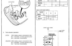
Power Door Locks Driver’s Door Actuator Test 1. Remove the door panel (see section 20). 2. Disconnect the 8-P connector from the actuator. ACTUATOR View from wide side 3. Test actuator operation: LOCK: With battery power connected to the No. 7 terminal, connect ground to the No. 8 terminal momentarily. UNLOCK: With battery power connected […]
Categories
nsxb23229a.pdf
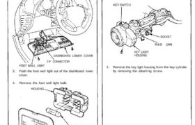
Foot Well Light Replacement 1. Remove the dashboard lower cover. 2. Disconnect the 2-P connector from the foot well light. DASHBOARD LOWER COVER 2-P CONNECTOR FOOT WELL LIGHT 3. Push the foot well light out of the dashboard lower cover. 4. Remove the foot well light bulb. HOUSING BULB (3.4W) LENS Ignition Key Light Replacement […]
Categories
nsxe23113a.pdf
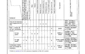
Troubleshooting NOTE: The numbers in the table show the troubleshooting sequence. *: Refer to section 22 for A/C pressure inspection of the A/C system Attachments nsxe23113a (159 kB)
Categories
nsxb23226a.pdf
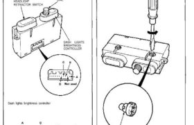
Dash Lights Brightness Control Controller Test 1. Remove the dash lights brightness controller from the instrument panel (see previous page). 2. Measure resistance between A and B terminals while rotating the adjusting dial. Resistance should vary from 0 to 20,000 ohms as the dial is rotated. NOTE: Resistance will vary slightly with temperature. HEADLIGHT RETRACTOR […]
Categories
nsxe23129a.pdf
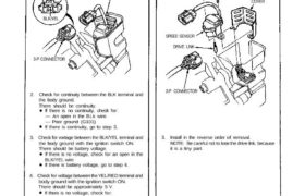
— Defective gauge assemble, check for the A21 Speed Sensor Input Test NOTE: Check the No. 2 (15 A) fuse in the under-dash fuse box, before testing. 1. Disconnect the 3-P connector from the speed sensor. View from terminal side SPEED SENSOR 3-P CONNECTOR 2. Check for continuity between the BLK terminal and the body […]
Categories
nsxd23110a.pdf
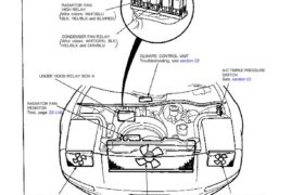
Radiator and Condenser Fan Controls Component Location Index UNDER HOOD RELAY BOX A RADIATOR FAN RESISTOR Test, page 23-116 RIGHT CONDENSER FAN MOTOR Test, page 23-117 Replacement, see section 22 RADIATOR FAN MOTOR Test, page 23-117 Replacement, see section 5 LEFT CONDENSER FAN MOTOR Test, page 23-117 Replacement, see section 22 A/C TRIPLE PRESSURE SWITCH […]
Categories
nsxb23257a.pdf
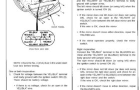
Function Test NOTE: Before testing, remove the left door panel, then disconnect all connectors from the door panel. 10-P CONNECTOR DOOR PANEL View from wire side NOTE: Check the No. 4 (15A) fuse in the under-dash fuse box before testing. One or both inoperative: 1. Check for voltage between the YEL/BLK1 terminal and body ground […]
Categories
nsxb23130a.pdf
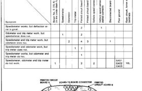
Speedometer/Trip Meter/Odometer Troubleshooting NOTE: The numbers in the table show the troubleshooting sequence. View from the back of the gauge assembly NOTE: A short to ground in the ORN wire can be caused by a short in any component connected to it. Vehicle Speed Sensor (VSS) Test Speedometer does not work. Inspect No. 5 (15 […]